Potter PFC-6030 User Manual
Page 103
6-97
PFC-6030 • 5403595 • Rev C • 2/13
Notification Appliance Circuits (NACs)
There are six (6) NAC circuits provided on the PSN-1000/PSN-1000(e) rated as continuous 3 amps at 24 vDC. The NAC
circuits may be configured for Class A or Class B. (Please refer to the Class A and B wiring examples shown in this section.)
The circuits reverse polarity upon activation and are marked accordingly on the board and illustrations.
NAC Wiring
Outputs are supervised and regulated.
•
NAC circuits are power limited.
•
Type of NAC output is selectable, and may be configured for strobe synchronization with Potter/AMSeCO, Wheelock®,
•
Gentex®, or System Sensor® strobe devices. Please refer to Potter document “5403592 NAC Compatibility Document”
for this information.
Class-A operation is accomplished by using a pair of NAC circuits (NAC 1&2, NAC 3&4 and NAC 5&6); this pairing
•
provides three (3) Class A circuits, each rated for a continuous 3 amps at 24 vDC.
NAC Maximum Impedance Formula
The maximum impedance is a function of the load being applied to the circuit. In order to calculate the maximum impedance as
follows:
(Alarm Current of Notification Appliances) x (Wire Resistance) < 3 Volts
NAC Wiring Configurations
examples of Class A and B follow.
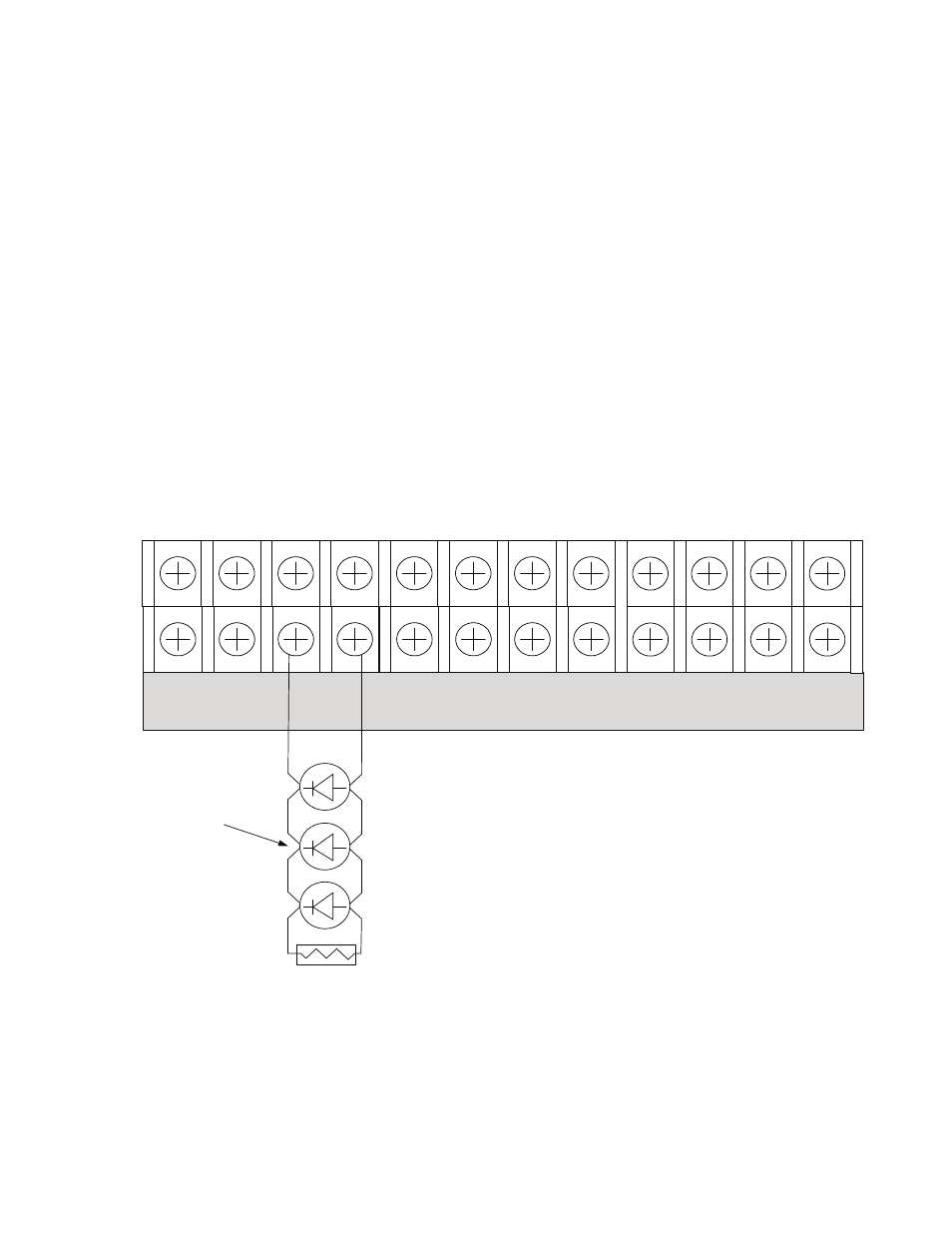
Class B NAC Wiring Example
Figure 136.
Notes:
The Potter part number for the listed end of line assembly is #3005013 eOL Resistor Assembly.
1.
The panel has ground fault detection on the NAC circuits. The impedance to ground for ground fault detection is 0 ohms.
2.
-
I1 + - NAC 1 + - NAC 5 + - NAC 3 +
-
+ A B
5.1k EOL
Potter Part #3005013
Notification
Appliance
-
I2 + - NAC 2 + - NAC 4 + - NAC 6 +
-
+ A B
P-LINK
DWG #602-24