3 i2c data buffer register (i2cbuf), 11 .4 .3 i, C data buffer register (i2cbuf) -10 – Maxim Integrated MAXQ622 User Manual
Page 165: C data buffer register (i2cbuf)
MAXQ612/MAXQ622 User’s Guide
11-10
Maxim Integrated
Bit 9: I
2
C Receiver Overrun Flag (I2CROI). This bit indicates a receive overrun when set to 1 . This bit is set to 1 if the
receiver has already received 2 bytes since the last CPU read . This bit is cleared to 0 by software reading the I2CBUF .
Setting this bit to 1 by software causes an interrupt if enabled . Writing 0 to this bit does not clear the interrupt .
Bit 8: I
2
C General Call Interrupt Flag (I2CGCI). This bit is set to 1 when the general call is enabled (I2CGCEN = 1)
and the general call address is received . This bit must be cleared to 0 by software once set . Setting this bit to 1 by
software causes an interrupt if enabled .
Bit 7: I
2
C NACK Interrupt Flag (I2CNACKI). This bit is set to 1 if the I
2
C transmitter receives a NACK from the receiver .
Setting this bit to 1 by hardware causes an interrupt if enabled . This bit must be cleared to 0 by software once set .
This bit is set by hardware only
Bit 6: I
2
C Arbitration Loss Flag (I2CALI). This bit is set to 1 when the I
2
C is configured as a master and loses in the
arbitration . When the master loses arbitration, the I2CMST bit is cleared to 0 . Setting this bit to 1 by hardware causes
an interrupt if enabled . This bit must be cleared to 0 by software once set . This bit is set by hardware only .
Bit 5: I
2
C Slave Address Match Interrupt Flag (I2CAMI). This bit is set to 1 when the I
2
C controller receives an
address that matches the contents in its slave address register (I2CSLA) during the address stage . This bit must be
cleared to 0 by software once set . Setting this bit to 1 by software causes an interrupt if enabled .
Bit 4: I
2
C Timeout Interrupt Flag (I2CTOI). This bit is set to 1 if either the I
2
C controller cannot generate a START
condition or the I
2
C SCL low time has expired the timeout value specified in I2CTO register . This happens when the
I
2
C controller is operating in master mode and some other device on the bus is using the bus or holding SCL low for
an extended period of time . This bit must be cleared to 0 by software once set . Setting this bit to 1 by software causes
an interrupt if enabled .
Bit 3: I
2
C Clock Stretch Interrupt Flag (I2CSTRI). This bit indicates that the I
2
C controller is operating with clock
stretching enabled and is holding the SCL clock signal low . The I
2
C controller releases SCL after this bit has been
cleared to 0 . Setting this bit to 1 by hardware causes an interrupt if enabled . This bit must be cleared to 0 by software
once set . This bit is set by hardware only .
Bit 2: I
2
C Receive Ready Interrupt Flag (I2CRXI). This bit indicates that a data byte has been received in the I
2
C
buffer . This bit must be cleared by software once set . Setting this bit to 1 by hardware causes an interrupt if enabled .
This bit is set by hardware only .
Bit 1: I
2
C Transmit Complete Interrupt Flag (I2CTXI). This bit indicates that an address or a data byte has been suc-
cessfully shifted out and the I
2
C controller has received an acknowledgment from the receiver (NACK or ACK) . This bit
must be cleared by software once set . Setting this bit to 1 by software causes an interrupt if enabled .
Bit 0: I
2
C START Interrupt Flag (I2CSRI). This bit is set to 1 when a START condition (S or Sr) is detected . This bit
must be cleared to 0 by software once set . Setting this bit to 1 by software causes an interrupt if enabled .
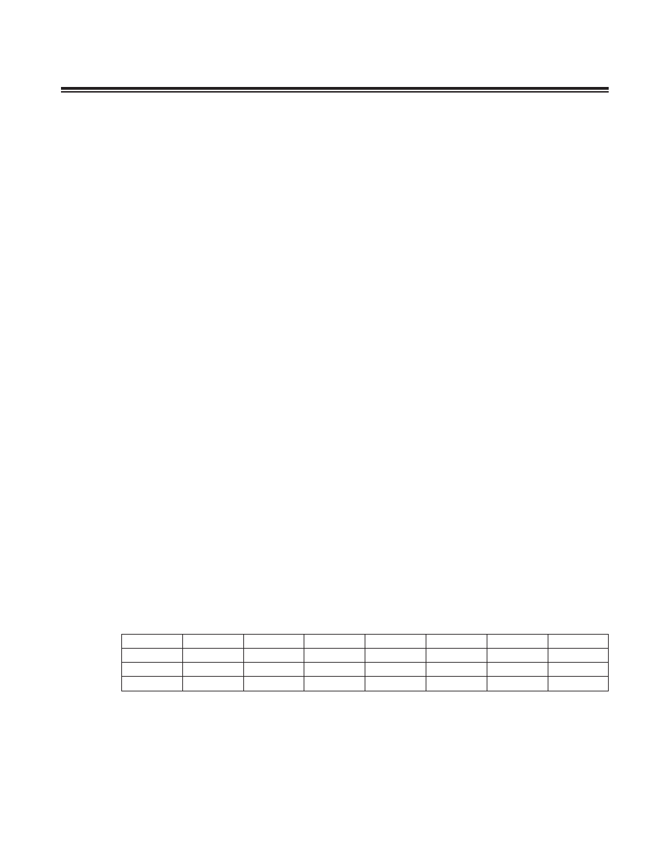
11.4.3 I
2
C Data Buffer Register (I2CBUF)
I
2
C Data Read and Write: Data for I
2
C transfer is read and written to this location . The I
2
C transmit and receive buffers
are internally stored separately, however, both are accessed through this buffer .
I
2
C Address Transmission: When transmitting an I
2
C address, the address should be loaded into I2CBUF[6:0] .
I2CBUF[7] is ignored and is not part of the I
2
C address .
Register Name
I2CBUF
Register Description
I
2
C Data Buffer Register
Register Address
M4[02h]
Bit #
7
6
5
4
3
2
1
0
Name
I2CBUF7
I2CBUF6
I2CBUF5
I2CBUF4
I2CBUF3
I2CBUF2
I2CBUF1
I2CBUF0
Reset
0
0
0
0
0
0
0
0
Access
rw
rw
rw
rw
rw
rw
rw
rw