2 ir control register b (ircnb), 8 .7 .2 ir control register b (ircnb) -11 – Maxim Integrated MAXQ622 User Manual
Page 135
MAXQ612/MAXQ622 User’s Guide
Maxim Integrated
8-11
Bits 5 and 4: IR Receive Edge Select Bits (IRRXSEL[1:0]) These bits define which edge of the input signal triggers
a receive capture function when enabled .
Bit 3: IR Data (IRDATA). This register bit defines how the carrier is modulated in transmit mode, and in receive mode, it
contains the state of IRRX when a qualified capture event happens . When IR transmit mode is in effect, setting IRDATA
= 1 enables the output of the carrier module (as affected by IRTXPOL) to be visible on the IRTX pin . When IRDATA =
0, the IR module is put in the idle state and IRTXPOL is output onto IRTX . In receive mode, the IRDATA bit contains the
latched state of the IRRX pin each time a capture event occurs .
Bit 2: IR TX Polarity Select (IRTXPOL). When the IR timer is enabled (IREN = 1), this bit selects the starting/idle logic
state and the carrier polarity for the transmit output . This bit also impacts the polarity of the IRTXM envelope when the
independent modulator transmit output mode is enabled (IRENV[1:0] =01b or 10b) . When IRENV[1:0] =01b or 10b,
the latched IRDATA bit is directly output to the IRTXM pin as the envelope when IRTXPOL = 0 . When IRTXPOL = 1, the
complement of the latched IRDATA bit is output .
Bit 1: IR Mode (IRMODE). This register bit controls the IR module operation mode .
Bit 0: IR Enable (IREN). This register bit enables the IR module . Setting this bit to 1 starts the operating mode as
defined by IRMODE bit . Clearing this bit to 0 terminates IR operation .
8.7.2 IR Control Register B (IRCNB)
Bit 3: Receive Carrier Burst-Count Enable (RXBCNT). Setting this bit to 1 enables the carrier burst-counting mode
for the IR timer when operating in receive mode . This bit is not meaningful for the transmit mode . Whenever software
changes RXBCNT from 0 to 1, the IRMT register is set to 0001h by hardware . When RXBCNT = 1, the IR timer receive
mode is modified in the following ways:
1) The IRV register is not captured to the IRMT register on detection of the IRRXSEL[1:0] selected edge(s) .
2) The IRMT register is incremented on detection of the IRRXSEL[1:0] selected edge(s) .
3) The IRIF flag is no longer set on capture-edge detection .
4) An IRCA x 2 interval timer is enabled and upon expiration, the IRIF flag is set .
When RXBCNT = 0, the receive carrier burst-count mode is disabled and normal receive capture functionality can be
used .
Bit 2: IR Interrupt Enable (IRIE). Setting this bit to 1 enables an interrupt to be generated to the CPU when the IR timer
overflow (IROV) or IR interrupt flag is set (IRIF) . Clearing this bit to 0 disables IR timer interrupt generation .
IRRXSEL[1:0]
IR RECEIVE MODE
00
Trigger on falling edge .
01
Trigger on rising edge .
10
Trigger on both rising and falling edge .
11
Reserved .
IRMODE
IR OPERATION MODE
0
Receive Mode
1
Transmit Mode
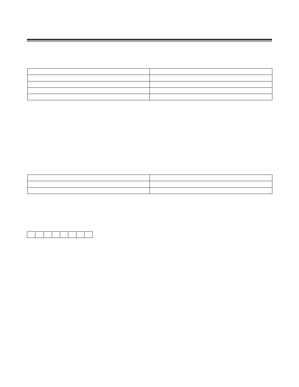
7
0
IR Control Register B (IRCNB)
0
rw
0
rw
0
rw
0
rw
0
rw
0
rw
0
rw
0
rw
Power-On Reset and System Resets
Read (r), Write (w), or Special (s) access