1 i2c mode of operation, 1 master-transmitter, 11 .1 i – Maxim Integrated MAXQ622 User Manual
Page 157: C mode of operation -2, 11 .1 .1 master-transmitter -2, Figure 11-1 . roles of i, C devices and direction of i, C signals -2, Table 11-1 . definition of i, C bus terminology -2
MAXQ612/MAXQ622 User’s Guide
11-2
Maxim Integrated
SECTION 11: I
2
C INTERFACE
The MAXQ612/MAXQ622 provide an I
2
C module, which is an 8-bit, bidirectional, 2-wire serial bus interface with the
following characteristics:
• Compliant with NXP I
2
C bus specification version 0 .3 (2007)
• Information is transferred through a serial-data bus (SDA) and a serial-clock line (SCL)
• Operates in either master or slave mode as a transmitter or receiver
• Supports a multimaster environment
• Supports a data transfer rate of up to 100kbps in standard mode and up to 400kbps in fast mode
• On-chip filtering rejects spikes on the bus data line to preserve data integrity
Therefore, any device that is attached to the I
2
C bus can assume one of the following roles:
1) Master-Transmitter
2) Master-Receiver
3) Slave-Transmitter
4) Slave-Receiver
Note that the above relationship is not permanent and is dependent on the direction of data transfer . In all cases, the
master is responsible for initiating the transfer and generating clock signals .
11.1 I
2
C Mode of Operation
The I
2
C module can be enabled by setting the I2CEN bit to 1 (I2CEN = 1) . The I
2
C module operates in master mode
if the I2CMST bit is set to 1 . The I
2
C master can choose to function as a transmitter (I2CMODE = 0) or as a receiver
(I2CMODE = 1) . To terminate a transfer, the master generates a STOP (P) condition by setting the I
2
C STOP bit to 1
(I2CSTOP = 1) .
11.1.1 Master-Transmitter
The I
2
C module functions as a master-transmitter when the master mode bit is set to 1 and the transfer mode bit is
cleared to 0 (I2CMST = 1 and I2CMODE = 0) . To initiate a transfer, the I
2
C master generates a START (S) condition by
setting the I
2
C START bit to 1 (I2CSTART = 1) . After successfully initiating the START condition, the master then writes
the slave address to I2CBUF and starts transmitting . On completion of a slave address transfer, the transmit interrupt
Table 11-1. Definition of I
2
C Bus Terminology
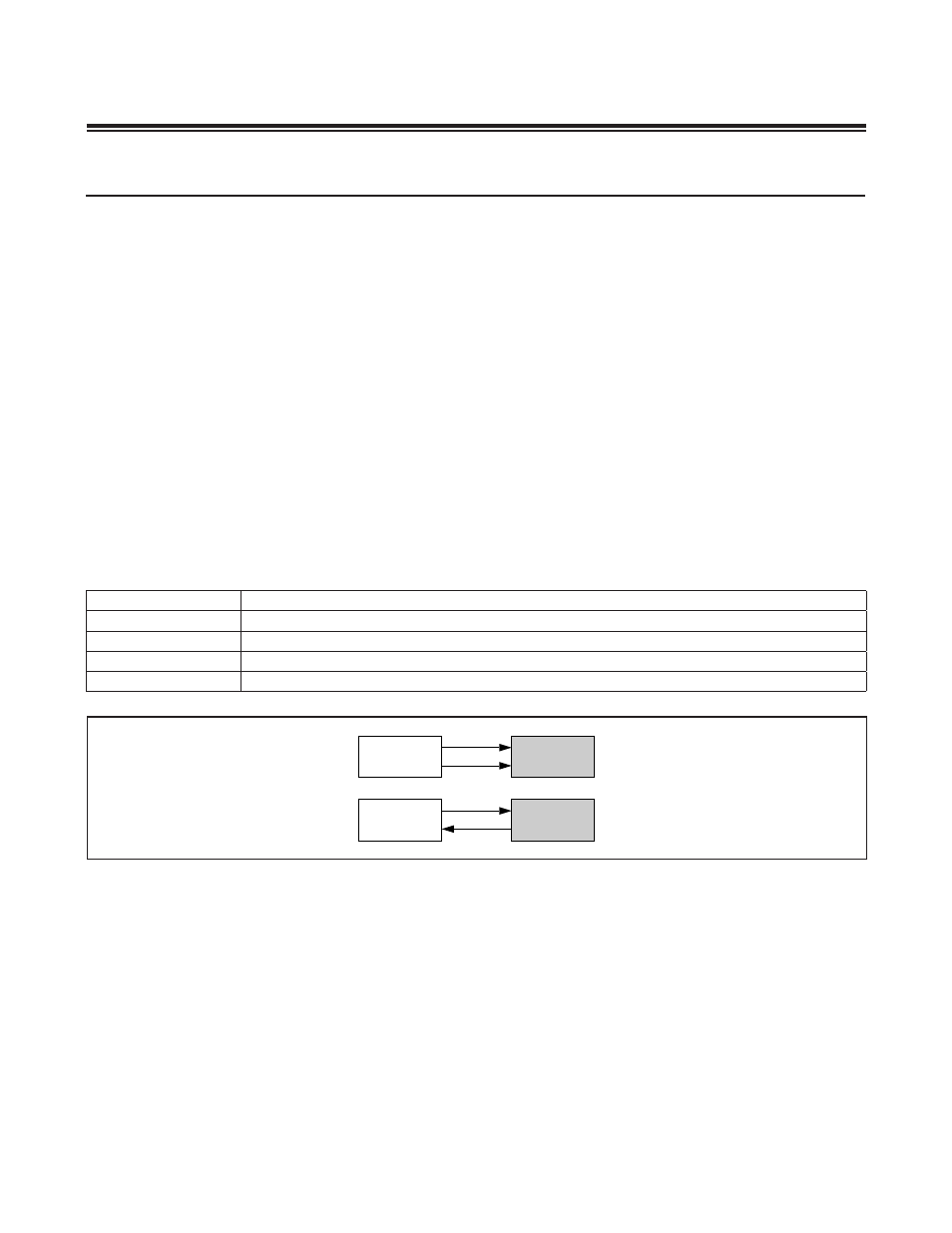
Figure 11-1. Roles of I
2
C Devices and Direction of I
2
C Signals
TERM
DESCRIPTION
Transmitter
The device that sends data to the bus .
Receiver
The device that receives data from the bus .
Master
The device that initiates a transfer, generates clock signals, and terminates a transfer .
Slave
The device addressed by a master .
MASTER
TRANSMITTER
SCL
SLAVE
RECEIVER
SDA
MASTER
RECEIVER
SCL
SLAVE
TRANSMITTER
SDA