6 timer b input clock, 2 timer/counter b peripheral registers, 1 timer b control register (tbcn) – Maxim Integrated MAXQ622 User Manual
Page 122: 7 .1 .6 timer b input clock -8, 7 .2 timer/counter b peripheral registers -8, 7 .2 .1 timer b control register (tbcn) -8, Table 7-3. timer b input clock prescaler selection
MAXQ612/MAXQ622 User’s Guide
7-8
Maxim Integrated
Example TBB output waveforms for the autoreload up/down-counting modes are shown below .
Up/down-count PWM duty cycle can be calculated as follows (where period = 2 x TBR):
Set mode
= (TBR + TBC)/(2 x TBR)
Reset mode
= TBC/(2 x TBR)
Toggle mode
= TBC/TBR or (TBR - TBC)/TBR
Note that the toggle mode has two possible duty-cycle calculations and depends upon the initial pin state and start-
ing TBV and TBC values . For example, the TBC/TBR equation would be used if the starting pin state were 1, TBV =
0, and 0 < TBC < TBR . If the starting pin state were 0, and all other initial conditions were the same, the (TBR - TBC)/
TBR equation would apply .
The set and reset up/down-count PWM modes effectively allow 17-bit resolution since the set mode allows duty-cycle
variation > 50% with 50% of the period always being high and the reset mode allows duty-cycle variation < 50% with
50% of the period always being low .
The toggle mode still effectively provides 16-bit PWM resolution with twice the period of the pure up-counting autore-
load mode .
7.1.6 Timer B Input Clock
The Timer B Input Clock can be prescaled using the TBPS[2:0] bits of the TBCN register . The Timer B input clock is
a divided version of the system clock as per the equation below (which also appears in the register bit descriptions) .
Timer B Clock = System Clock/2
(2xTBPS[2:0])
The TBPS[2:0] bits should be configured by the user when the timer is stopped (TRB = 0) . While hardware does not
prevent changing the TBPS[2:0] bits when the timer is running, the resultant behavior is indeterministic .
7.2 Timer/Counter B Peripheral Registers
7.2.1 Timer B Control Register (TBCN)
Bit 15: (TBCN.15) Counter/Timer Select (C/TB). This bit determines whether Timer B functions as a timer or counter .
Setting this bit to 1 causes Timer B to count negative transitions on the TBA pin . If this bit is cleared to 0 Timer B func-
tions as a Timer . The speed of Timer B is determined by the TBPS[2:0] bits of TBCN .
Bits 14 and 13: Reserved . Reads return 0 .
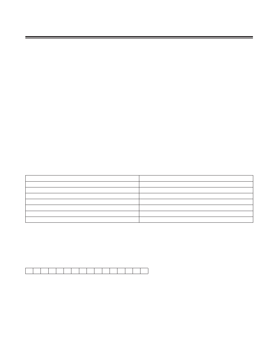
Table 7-3. Timer B Input Clock Prescaler Selection
TBPS[2:0]
TIMER B INPUT CLOCK
000
Sysclk/1
001
Sysclk/4
010
Sysclk/16
011
Sysclk/64
100
Sysclk/256
101
Sysclk/1024
11x
Sysclk/1
15
0
Timer B Control Register (TBCN)
0
rw
0
rw
0
rw
0
rw
0
rw
0
rw
0
rw
0
rw
0
rw
0
rw
0
rw
0
rw
0
rw
0
rw
0
rw
0
rw
Power-On Reset and System Resets
Read (r), Write (w), or Special (s) access