2 timer b mode: up/down-count pwm output mode – Maxim Integrated MAXQ622 User Manual
Page 121
MAXQ612/MAXQ622 User’s Guide
Maxim Integrated
7-7
The set and reset functions for the autoreload up-counting mode essentially provide the same functionality . They pro-
vide a 16-bit PWM with the ability to change the frequency using the TBR reload value . The toggle mode allows a 50%
duty cycle waveform to be created (when the TBC register is configured to a value inside the counting range, i .e ., 0 <
TBC < TBR, with Timer B running) . With the TBC register outside of the count range, the set and reset functions allow a
timed clear or set of a given pin without need of polling or interrupting the CPU such that it can manually be performed .
Up-count set, reset PWM duty cycle can be calculated as follows (where period = TBR + 1):
Set mode
= (TBR - TBC)/(TBR + 1)
Reset mode
= TBC/(TBR + 1)
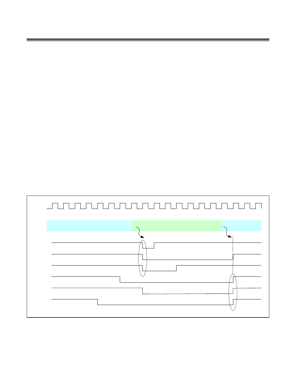
7.1.5.2 Timer B Mode: Up/Down-Count PWM Output Mode
The 16-bit up/down-count timer is utilized for the up/down-count PWM output mode to produce center-aligned PWM
output . When the Timer B is configured in the up/down-count mode, the external pin (TBB) is used to control the direc-
tion of the timer count . When the Timer B PWM output functionality is enabled at the same time as the up/down-count
autoreload mode, the TBB pin no longer controls the direction of counting . Instead, the up/count count is controlled
internally . When the timer is up counting upward and reaches TBR, in the next cycle, it reverses its direction of count-
ing . When the timer is down counting and reaches 0000h, it reverses direction so as to begin up counting (as illustrated
in Figure 7-6) . When the up/down autoreload and PWM output modes are both enabled, the TBB input function can
still be enabled by the EXENB = 1 configuration . Enabling the TBB input function during this mode allows detection
of PWM output negative edges to set the EXFB interrupt flag . Note that the EXFB flag can be set independent of the
state of the TRB bit (e .g ., EXFB can still be set on detection of a negative edge when TRB = 0) . While it is most likely
that TRB = 1 when EXFB is set, since TRB = 1 is required to enable the PWM output, a negative edge on the TBB pin
while TRB = 0 can still result in setting of EXFB . Using the standard GPI/O port controls to generate a negative edge
when the PWM is not running, for instance, can set EXFB .
Figure 7-6. Timer B PWM Output Up/Down-Count Examples
1 2 3 4 5 6 7 8 7 6 5 4 3 2 1 0 1 2 3
UP
TBR = 0008h
TBV = 0000
TBB PIN
SET, TBC = 7
SET, TBC = 0
SET, TBC = 5
SET, TBC = 6
SET, TBC = 8
SET, TBC = 4
UP
DOWN