1 anode replacement – AERCO Innovation (G-14-2265 and above) User Manual
Page 86
Innovation Water Heaters Installation, Operation & Maintenance Manual
CHAPTER 6 – MAINTENANCE
Page 86 of
206
AERCO International, Inc. • 100 Oritani Dr. • Blauvelt, NY 10913
OMM-0078_0L
PRI: 11/25/2014
Phone: 800-526-0288
GF-128
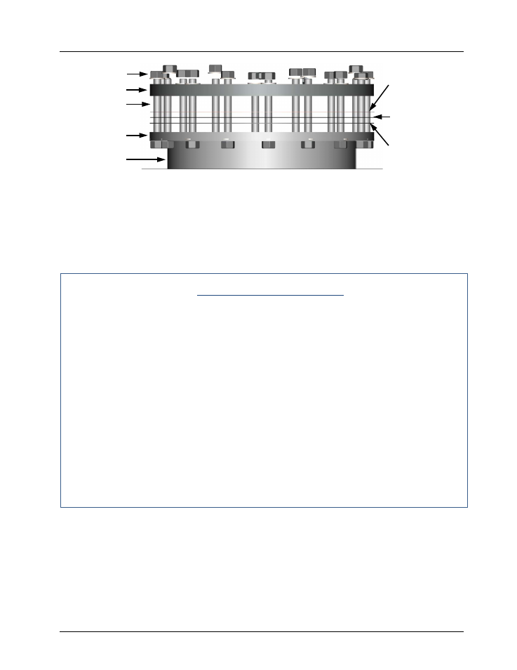
Figure 6-7. Heat Exchanger Head Configuration
6.7.1 Anode Replacement
If your inspection of the unit’s anode blocks reveal that they have shrunk by more than 40%
(original dimensions are 7 1/4" X 4”), refer to Figure 6-8 and complete the instructions below to
install the Anode Replacement Kit (P/N 24430).
Anode Block Replacement
1.
Cut a doughnut shaped piece of cardboard that will fit snugly inside the heat exchanger
shell and around the combustion chamber head and fit it in place above the heat exchanger
tubes. This will act as a shield to prevent any hardware or debris from dropping into the
chamber during installation.
2.
Referring to Figure 6-8, remove the four (4) 1/4–20 hex bolts holding the anode blocks to
the anode mounting bracket, and then remove both old anode blocks.
3.
Position the four (4) ‘O’ rings (P/N 88019) in the circular recesses around the threaded
holes in the new anode blocks (P/N 44174). The ‘O’ rings keep water from entering the
threaded holes, preventing them from corroding, which would shorten the anode’s life.
4.
Fasten one anode block to the mounting bracket with two (2) 1/4–20 hex flange seal bolts
(P/N 54108) and fully tighten them. Note that these are specialized bolts, with built-in ‘O’
rings –
DO NOT substitute off-the-shelf bolts of the same size. DO NOT over-tighten
these bolts
.
5.
Repeat the previous step to attach the second anode block to the mounting bracket.
6.
Remove any hardware or debris that may have fallen on the cardboard shield installed in
step 1 and then remove the shield from the chamber.
5/8-11 X 3-3/4”
STUD
5/8-11 HEX
UPPER HEAD
SHELL FLANGE
HEAT
EXCHANGER
UPPER HEAD LINER
(P/N 123077)
HEAD RELEASE
GASKET (P/N GP-18556)
SHELL GASKET
(P/N GP-18532)