AERCO Innovation (G-14-2265 and above) User Manual
Page 73
Innovation Water Heaters Installation, Operation & Maintenance Manual
CHAPTER 5 – SAFETY DEVICE TESTING
OMM-0078_0L
AERCO International, Inc. • 100 Oritani Dr. • Blauvelt, NY 10913
Page 73 of
206
GF-128
Phone: 800-526-0288
PRI: 11/25/2014
Air Flow Fault Tests – Continued
4.
The unit should perform two IGNITION RETRY cycles and then shut down on the third
successive ignition attempt. The unit will display AIRFLOW FAULT DURING PURGE.
5.
Re-enable the blower output drive voltage by performing the following steps:
(a)
Press the MENU key until CONFIGURATION MENU is displayed.
(b)
Press the ▲ arrow key until the ANALOG OUTPUT function is displayed, then
press the CHANGE key.
(c)
Press the ▲ arrow key until VALVE POSITION 0-10V is displayed, then press the
ENTER key.
6.
Once the unit has proved flame, turn off the blower by going to the Configuration Menu,
Analog Output menu item and select OFF.
7.
The Blower Proof Switch will open and the blower should stop. The unit should shut down
and display AIRFLOW FAULT DURING RUN.
8.
Go to the Configuration Menu, Analog Output item and select VALVE POSITION 0-10v.
9.
Press the CLEAR button. The unit should restart.
10.
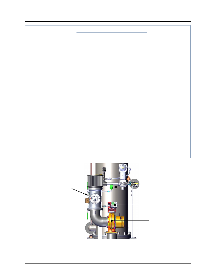
Next, check the operation of the Blocked Inlet Switch located on the inlet side of the
Air/Fuel Valve (Figure 5-4).
11.
Ensure that the sheet metal panels are securely installed on the water heater and the unit
is running.
12.
At the rear of the unit, partially block the air inlet (Figure 5-5) with a plywood sheet or
metal plate.
13.
The unit should shut down and again display AIRFLOW FAULT DURING RUN.
14.
Unblock the air inlet and press the CLEAR button. The unit should restart.
PARTIAL FRONT VIEW
Figure 5-4. Blower Proof & Blocked Inlet Switch Locations
AIR/FUEL
VALVE
BLOWER
BLOCKED
INLET SWITCH
BLOWER PROOF
SWITCH