8 pressure & temperature relief valve installation – AERCO Innovation (G-14-2265 and above) User Manual
Page 23
Innovation Water Heaters Installation, Operation & Maintenance Manual
CHAPTER 2 – INSTALLATION
OMM-0078_0L
AERCO International, Inc. • 100 Oritani Dr. • Blauvelt, NY 10913
Page 23 of
206
GF-128
Phone: 800-526-0288
PRI: 11/25/2014
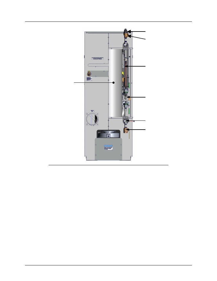
REAR VIEW – RIGHT-REAR PANEL & EXHAUST VENT REMOVED
Figure 2-5. Recirculation Loop
NOTE
The maximum working pressure for installations within the Province of
Alberta is 87 psig. Therefore, a pressure & temperature relief valve with a
setting of 75 psig/190°F is supplied with Alberta shipments.
2.8 PRESSURE & TEMPERATURE RELIEF VALVE INSTALLATION
An ASME rated Pressure & Temperature (P&T) Relief Valve is factory installed on each
Innovation water heater on the hot water outlet at the top of the Recirculation Loop Assembly as
shown in Figure 2-5. With the exception of Alberta installations (see above Note), the valve
setpoint is 150 psig/190°F.
A suitable pipe joint compound should be used on the threaded connections. Any excess should
be wiped off to avoid getting any into the valve body. The relief valve should be piped to within
12 inches of the floor to prevent injury in the event of a discharge. The relief outlet piping must
be equal to the outlet size of the relief valve without reduction. No valves, restrictions, or other
RECIRCULATION
LOOP PIPING
HOT WATER OUTLET
P&T VALVE
RECIRCULATION
PUMP
COLD WATER INLET
DRAIN VALVE
HEAT EXCHANGER