AERCO Innovation (G-14-2265 and above) User Manual
Page 82
Innovation Water Heaters Installation, Operation & Maintenance Manual
CHAPTER 6 – MAINTENANCE
Page 82 of
206
AERCO International, Inc. • 100 Oritani Dr. • Blauvelt, NY 10913
OMM-0078_0L
PRI: 11/25/2014
Phone: 800-526-0288
GF-128
Fireside Inspection - Continued
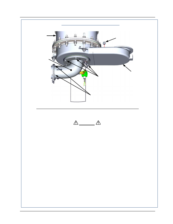
PARTIAL RIGHT-SIDE VIEW – SUPPORT BRACKET REMOVED FOR CLARITY
Figure 6-3. Blower-Side Intake Manifold & Exhaust Manifold Locations
The intake manifold, burner and exhaust manifold assemblies weigh
approximately 25 pounds. Use care when removing these assemblies in the
following steps.
11.
While supporting the blower-side intake manifold, loosen and remove the six (6) 5/16-18
hex nuts securing it to the studs protruding from the exhaust manifold.
12.
Carefully lower and remove the blower side intake manifold, burner assembly and both
burner gaskets (P/N GP-18899). See Figures 6-3 and 6-4.
13.
Disconnect the exhaust temperature sensor (Figure 6-3) by unscrewing it from the exhaust
manifold.
14.
While supporting the exhaust manifold, remove the two (2) side nuts (Figure 6-5) securing
the manifold to the heat exchanger. Loosen, but do not remove the third nut nearest to the
front of the unit.
15.
Remove the exhaust manifold from the unit.
16.
Inspect the exhaust manifold and burner assemblies for debris. Clean out debris as
necessary.
17.
This completes the fireside inspection of the unit. Proceed to step 18 and reassemble the
unit as indicated.
CAUTION
EXHAUST
MANIFOLD
HEAT
EXCHANGER
BLOWER
SIDE INTAKE
MANIFOLD
5/16-18 HEX
NUTS (6)
CAP SCREWS
1/4-20 X 7/8” LG. (4)
EXHAUST
SENSOR