AERCO Innovation (G-14-2265 and above) User Manual
Page 51
Innovation Water Heaters Installation, Operation & Maintenance Manual
CHAPTER 3 – OPERATION
OMM-0078_0L
AERCO International, Inc. • 100 Oritani Dr. • Blauvelt, NY 10913
Page 51 of
206
GF-128
Phone: 800-526-0288
PRI: 11/25/2014
Start Sequence – Continued
4.
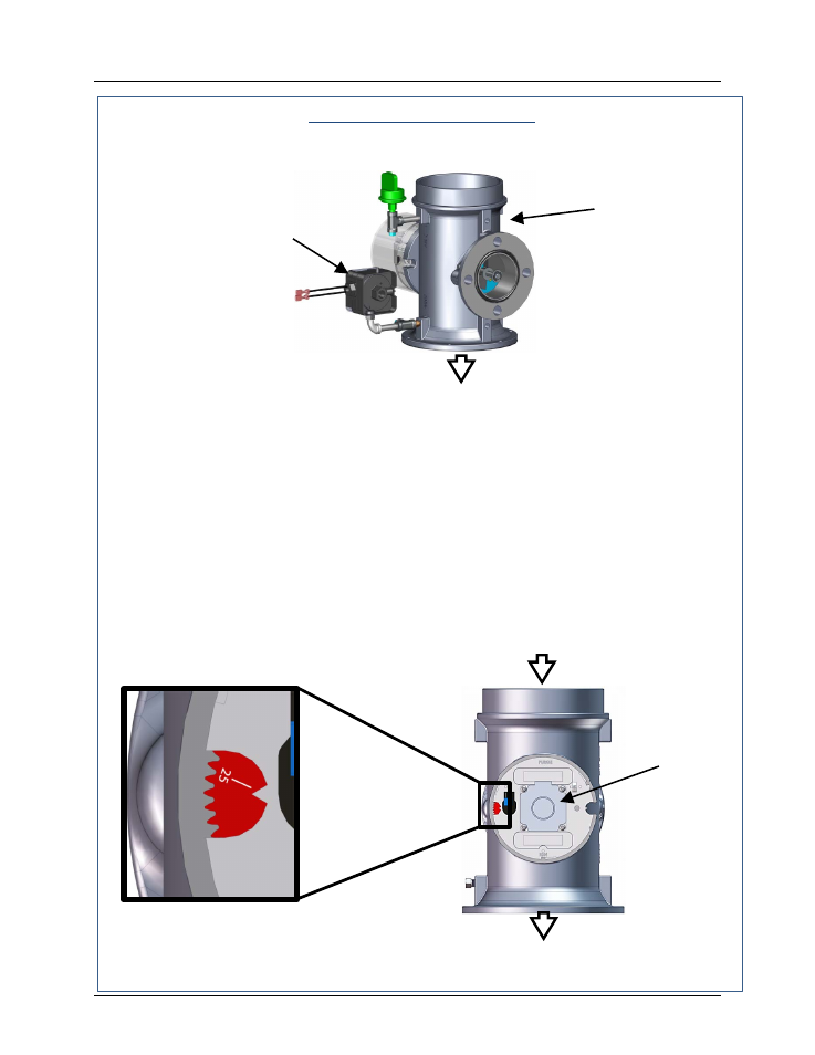
Next, the blower proof switch on the Air/Fuel Valve (Figure 3-5) closes. The display will
show Purging and indicate the elapsed time of the purge cycle in seconds.
Figure 3-5. Blower Proof Switch
5.
Upon completion of the purge cycle, the Control Box initiates an ignition cycle and the
following events occur:
(a)
The Air/Fuel Valve rotates to the low-fire ignition position and closes the ignition
switch. The dial on the Air/Fuel Valve (Figure 3-6) will read between 25 and 35
to indicate that the valve is in the low-fire position.
(b)
The igniter-injector
relay is activated and provides ignition spark.
(c)
The gas Safety Shut-Off Valve (SSOV) is energized (opened) allowing gas to
flow into the Air/Fuel Valve.
Figure 3-6. Air/Fuel Valve In Ignition Position
BLOWER
PROOF
SWITCH
OUTLET TO BLOWER
AIR/FUEL
VALVE
IGNITION
VALVE
POSITION
DIAL AT
25% to 35%
STEPPER
MOTOR
TO BLOWER
AIR IN