Detection mode, Detection mode -8 – KEYENCE FS-N10 Series User Manual
Page 54
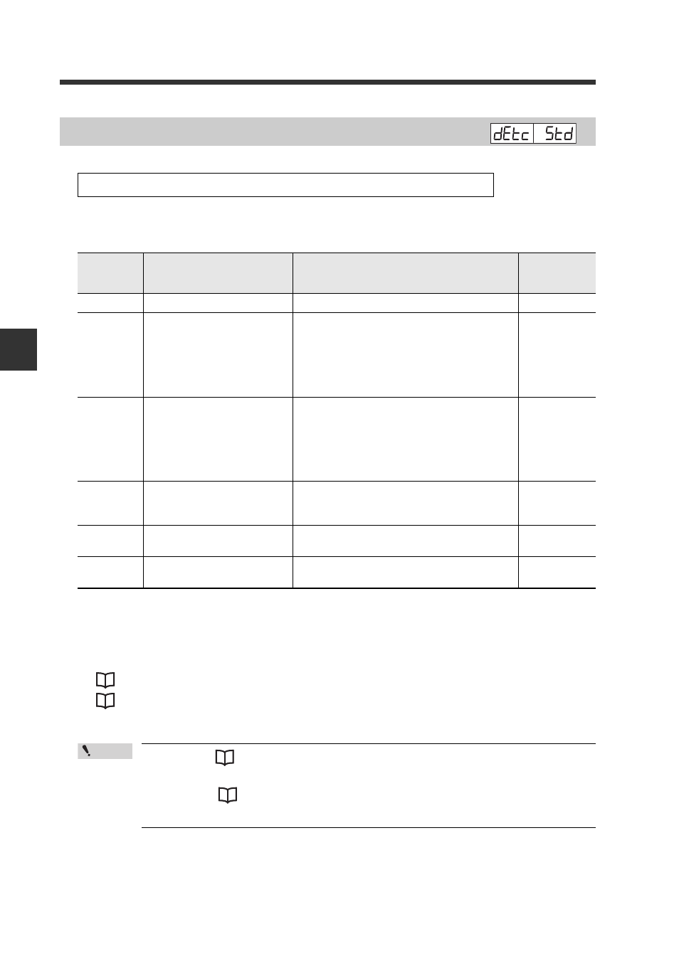
4-3 Detection Settings (Func)
4
Set
tings
f
o
r
Ad
v
an
ced F
u
nct
ion
s
4-8
- Digital Fiber Sensor FS-N10 Series User's Manual -
The table below lists the detection modes that can be selected.
*
In the DATUM mode, correction intervals can be set in the range of
LEv1
to
LEv3
.
The default is
LEv1
.
Also, the warning output level can be set in the range of
0P
(0%) to
100P
(100%).
The default is
50P
.
"Adjusting the correction interval" (page 4-12)
"Changing the warning output level" (page 4-13)
• Refer to
"Detection Mode for Output2" (page 4-35) for details on
the 2-output type channel 2 detection mode.
• Refer to
"Restrictions on Each Detection Mode" (page 6-9) for
restrictions on the sensitivity setting methods.
Detection Mode
Refer to page 4-2 "Detection Settings (Func)" for setting methods.
Display
Detection mode
Function
Reference
page
Std
Normal detection
Normal detection mode (Default)
-
dtM1
DATUM1 mode
*
The received light intensity when
there is no workpiece is always cali-
brated to "
100.0
", and the setting
value is also calibrated so that the
setting value and received light inten-
sity ratio is always constant.
dtM2
DATUM2 mode
*
The received light intensity when
there is no workpiece is always cali-
brated to "
.0
", and the setting value is
also calibrated so that the setting
value and received light intensity ratio
is always constant.
ArEA
Area detection mode
Detection is made only when the
received light intensity goes out of a
given range.
_|~d
Rising edge detection
mode
Detection is made only when the
received light intensity increases.
~L_d
Falling edge detection
mode
Detection is made only when the
received light intensity decreases.
Point