Wiring diagrams for sensor amplifiers, Wiring diagrams for cable types, Wiring diagrams for sensor amplifiers -4 – KEYENCE FS-N10 Series User Manual
Page 18
2-1 Installing Sensor Amplifiers
2
Inst
al
la
ti
on and
Conn
ect
ion
2-4
- Digital Fiber Sensor FS-N10 Series User's Manual -
· Be sure to turn off the power before wiring.
· Insulate each input or output cable that will not be used.
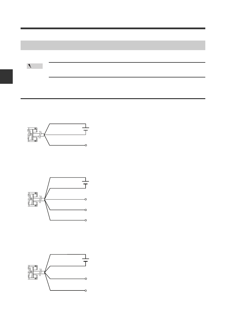
Wiring Diagrams for Cable Types
1-output type (FS-N11
/N12
)
2-output type (FS-N13
/N14
)
Monitor output type (FS-N11MN)
Wiring Diagrams for Sensor Amplifiers
Point
Brown
*
Output
Blue
*
Black
12 to 24 VDC
* FS-N11N/N11P only
Brown
*
Blue
*
Black
12 to 24 VDC
* FS-N13N/N13P only
Output1
External input
Output2
White
Pink
Brown
Blue
12 to 24 VDC
* Connect to a device having an input
impedance 10 k
Ω
or more.
Black
Output
Monitor output
1 to 5V
Orange
*
See also other documents in the category KEYENCE Sensors:
- LR-TB2000 Series (12 pages)
- LR-TB5000 Series (12 pages)
- LR-ZB250AN/AP (4 pages)
- LR-ZB250AN/P (3 pages)
- LR-ZBxN/P Series (3 pages)
- LR-ZBxxB (3 pages)
- OP-85135 (1 page)
- PZ-G Series (2 pages)
- PZ-V/M (2 pages)
- PS-N10 Series (12 pages)
- PX-10 (10 pages)
- CZ-V21A(P) (10 pages)
- CZ-K1(P) (8 pages)
- CZ-V1 (8 pages)
- FS-N10 Series (6 pages)
- FS-N15CN (1 page)
- FU-93(Z) (2 pages)
- FU-V Series (2 pages)
- FS-V30 (6 pages)
- FU-A40 (1 page)
- NU/FS-N Series (16 pages)
- FS-V33(P) (8 pages)
- FS-V21 (4 pages)
- FS-V22 (4 pages)
- FS-V11(P) (4 pages)
- FS-V1(P) (4 pages)
- LV-N10 Series (12 pages)
- LV-N10 Series (112 pages)
- LV-S62 (1 page)
- OP-84350 (1 page)
- LV-SA (10 pages)
- LV-SB (12 pages)
- OP-87305 (1 page)
- LV Series (10 pages)
- LV-B102 (1 page)
- EV-108M(U) (1 page)
- EZ Series (1 page)
- EM Series (1 page)
- ES-M1(P) (3 pages)
- EX-V Series (120 pages)
- EX-500(W) Series (16 pages)
- GV Series (10 pages)
- IA Series (8 pages)
- LB-1000(W) (24 pages)