Network diagram, Setup, A p p e n d i x – Cisco 12000/10700 V3.1.1 User Manual
Page 583
C-1
Cisco 12000/10700 v3.1.1 Router Manager User Guide
OL-4455-01
A P P E N D I X
C
Investigating LSP Black Holes Using Cisco 12000
Series Router Manager
Network Diagram
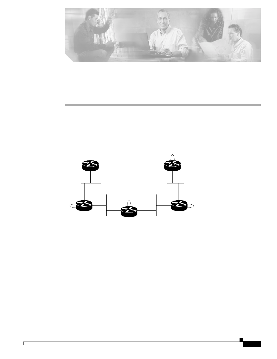
Figure C-1
Example Network Diagram
Setup
On a U10 running the Solaris 8 operating system, the following was installed:
•
Cisco EMF 3.2 with required patches
•
Cisco 12000/10720 Router Manager
A Cisco 12000/10720 Router Manager chassis was deployed with the IP address of the P router as shown
in
. The object was commissioned to discover all interfaces. The links shown in
comprise of the following technologies:
•
CE1—PE1: Fast Ethernet
•
PE1—P :Gigabit Ethernet
CE1
(cl-7505-1)
CE2
(cl-7505-2)
PE2
(cl-7505-3)
P
(cl-12008-1)
10.7.7.7
PE1
(cl-7505-1)
192.168.1.196/26
93226
10.10.10.0/24
10.1.1.0/24
10.5.5.5
10.2.2.2
10.6.6.0/24
.2
.5
.1
.6
.2
.5
.7
.7