Brookfield DV-III Ultra Rheometer User Manual
Page 29
Brookfield Engineering Laboratories, Inc.
Page 29
Manual No. M/98-211-B0104
Brookfield Engineering Laboratories, Inc.
Page 29
Manual No. M98-211-E0912
Note:
If you are using an accessory device such as a Small Sample Adapter,
the complete kit must be configured for the EZ-Lock Unit to ensure
proper alignment and spindle immersion. Contact Brookfield for more
information.
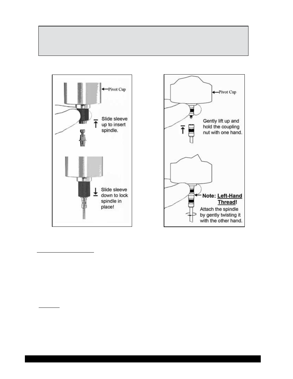
Figures III-1a and III-1b shows the method for both connection systems.
Figure III-1a: EZ-Lock
Figure III-1b: Standard Spindle
Standard Threaded Shaft
The spindles are attached to the viscometer by screwing them onto the lower shaft. Note that the
spindles have a left-handed thread. The lower shaft should be secured and slightly lifted with one
hand while screwing the spindle to the left. The face of the spindle nut and the matching surface
on the lower shaft should be smooth and clean to prevent eccentric rotation of the spindle. Spindles
can be identified by the number on the side of the spindle coupling nut.
EZ-Lock
Hold the spindle with one hand while gently raising the spring-loaded outer sleeve to its highest
position with the other hand. Insert the EZ-Lock Spindle Coupling so that the bottom of the coupling
is flush with the bottom of the sleeve, and lower the sleeve. The sleeve should easily slide back
down to hold the spindle/coupling assembly in place for use. [Spindles can be identified by entry
code; look for the number on the side of the EZ-Lock spindle coupling.]