Brookfield DV-III Ultra Rheometer User Manual
Page 109
Brookfield Engineering Laboratories, Inc.
Page 109
Manual No. M/98-211-B0104
Brookfield Engineering Laboratories, Inc.
Page 109
Manual No. M98-211-E0912
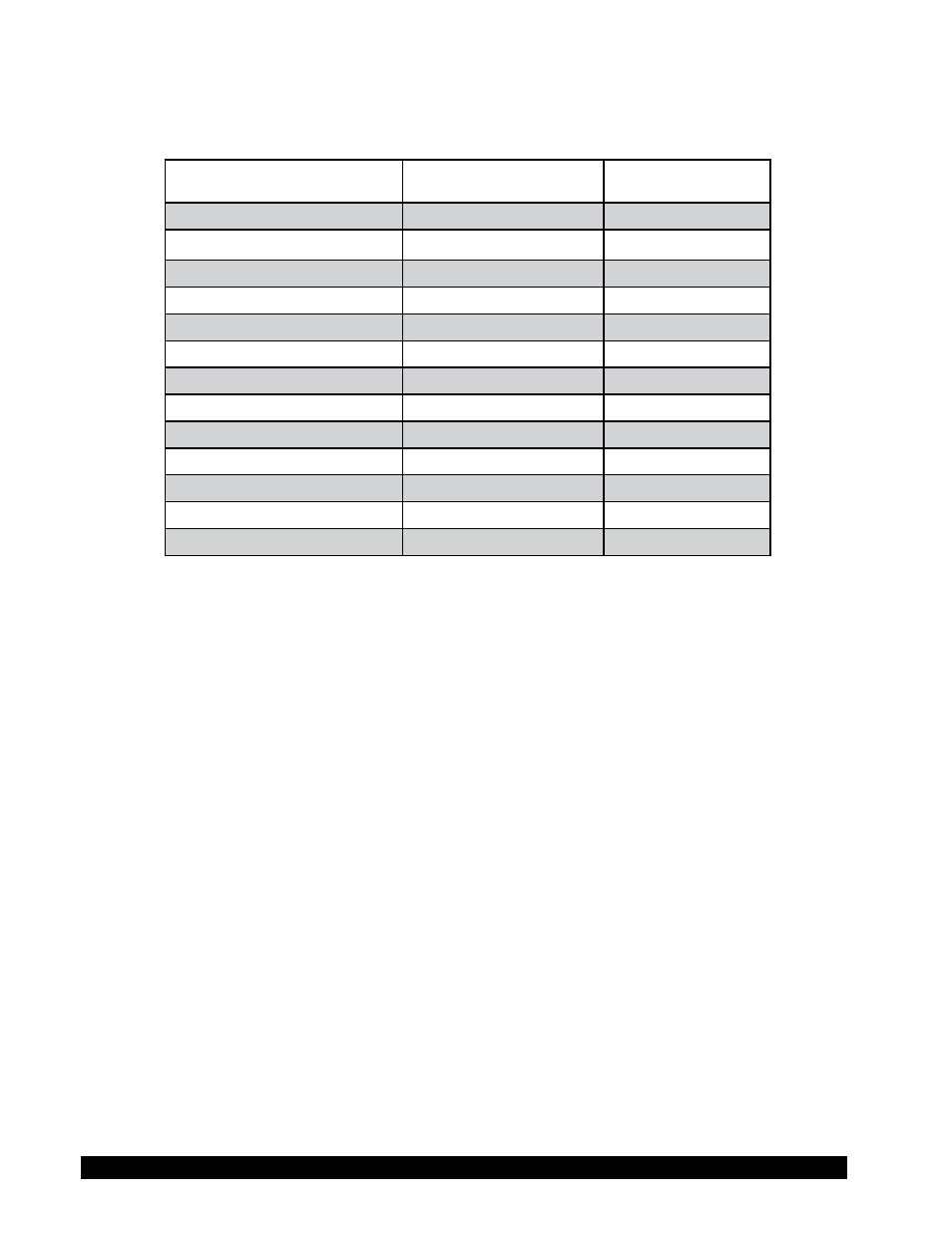
Table D-2 lists the model codes and spring torque constants for each Rheometer model.
Table D-2
MODEL
TK
MODEL CODE ON
DV-III ULTRA SCREEN
LVDV-III Ultra
0.09373
LV
2.5xLVDV-III Ultra
0.2343
4L
5xLVDV-III Ultra
0.4686
5L
1/4 RVDV-III Ultra
0.25
1R
1/2 RVDV-III Ultra
0.5
2R
RVDV-III Ultra
1
RV
HADV-III Ultra
2
HA
2xHADV-III Ultra
4
3A
2.5xHADV-III Ultra
5
4A
HBDV-III Ultra
8
HB
2xHBDV-III Ultra
16
3B
2.5xHBDV-III Ultra
20
4B
5xHBDV-III Ultra
40
5B
The full scale viscosity range for any DV-III Ultra model and spindle may be calculated using the
equation:
Full Scale Viscosity Range [cP] = TK ∗ SMC ∗
10,000
______
RPM
Where:
TK
= DV-III Ultra Torque Constant from Table D-2
SMC = Spindle Multiplier Constant listed in Table D-1
The Shear Rate calculation is:
Shear Rate (1/sec)
=
SRC * RPM
Where:
SRC = Shear Rate Constant from Table D-1
Using Non-standard spindles with DV-III Ultra and RHEOCALC Software
Spindle Entry 99 allows entry of spindle constants which the DV-III Ultra will use to calculate
Viscosity, Shear Rate and Shear Stress for spindles in boundary conditions other than the 600ml
beaker or specified chamber.
The spindles must conform to geometries that allow for mathematical calculations of Shear Rate
and Shear Stress i.e. coaxial cylinder.