Brookfield DV-III Ultra Rheometer User Manual
Page 126
Brookfield Engineering Laboratories, Inc.
Page 126
Manual No. M98-211-E0912
xx
=
The firmware version of the instrument (i.e. version 4.1 is returned as 41)
mm
=
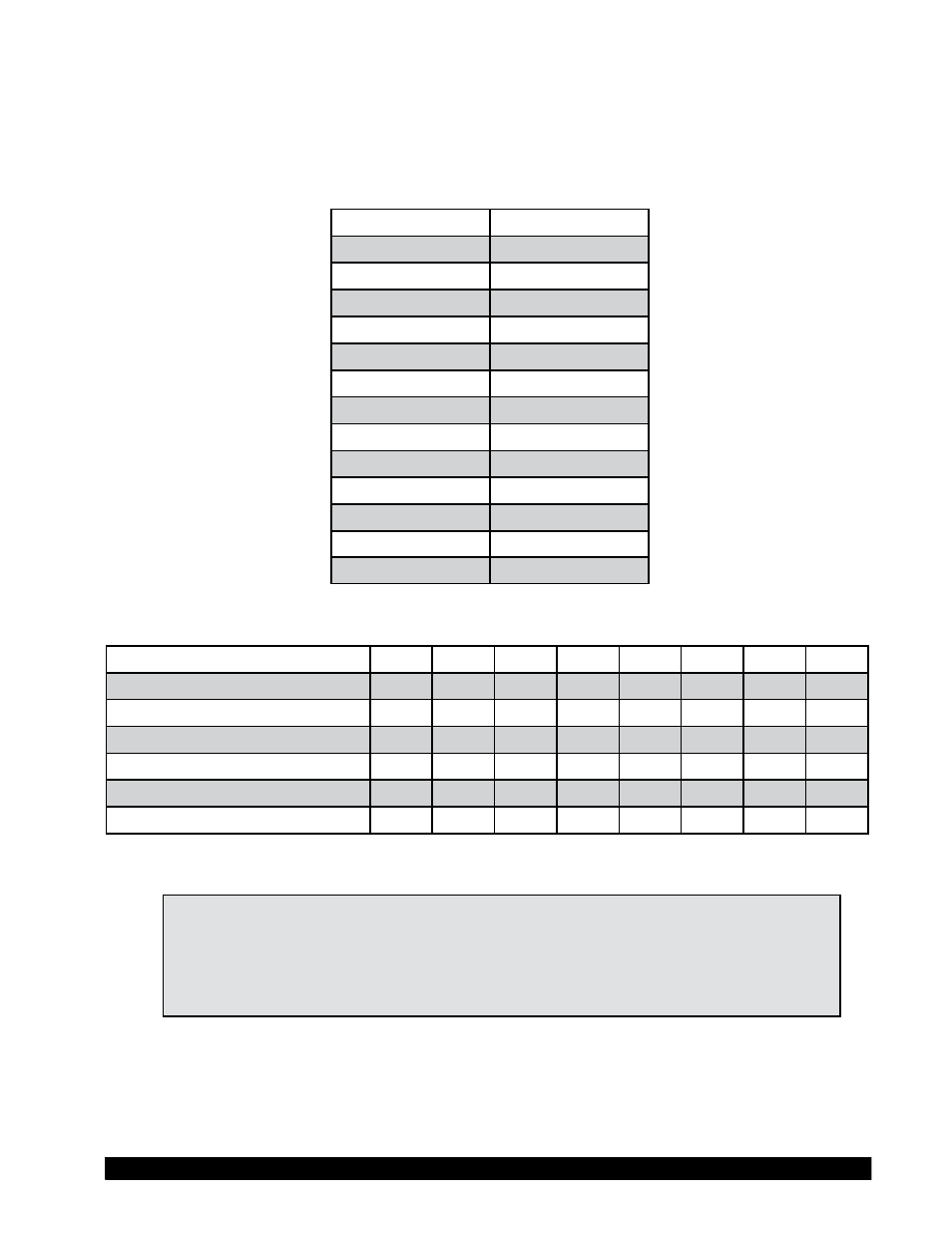
These 2 characters will be used to represent the model for which the DV-III+ is
configured. The model decoding is shown in Table I-2 below.
MODEL
mm
LV
LV
2.5LV
4L
5LV
5L
RV
RV
RV
1R
RV
2R
HA
HA
2HA
3A
2.5HA
4A
HB
HB
2HB
3B
2.5HB
4B
5HB
5B
Table I-2 - DV-III Ultra Model Decoding
Invalid cmd received
1
x
x
x
x
x
x
x
Diagnostics error
x
x
1
x
x
x
x
x
Motor circuit error
x
x
x
1
x
x
x
x
Auto-zero complete
x
x
x
x
1
x
x
x
Motor speed = 0
x
x
x
x
x
1
x
x
Motor On (Energized)
x
x
x
x
x
x
1
x
Control circuitry enabled
x
x
x
x
x
x
x
1
Table I-3 - Status Byte
Note:
These values are not updated in the status byte when the listed condition
occurs. They are made available when the computer next sends a
command that includes the status byte in the response. The flags are
cleared when the condition causing a flag to be set has been resolved
or by re-enabling (E command) the DV-III-Ultra.
The DV-III Ultra must first be issued the E(nable) command to enable control circuitry and ascertain its
current status. The DV-III Ultra will respond with an echo of the E(nable) command and will append
the current status <ss> of the DV-III Ultra. This 2-digit status byte will provide information as to the
rheometer's internal working condition and capability to continue with or to accept new tasks.