Plan equipment location – Welch Allyn Acuity LT Mobile - Installation Guide User Manual
Page 11
Installation Guide
Chapter 2 Plan the installation
7
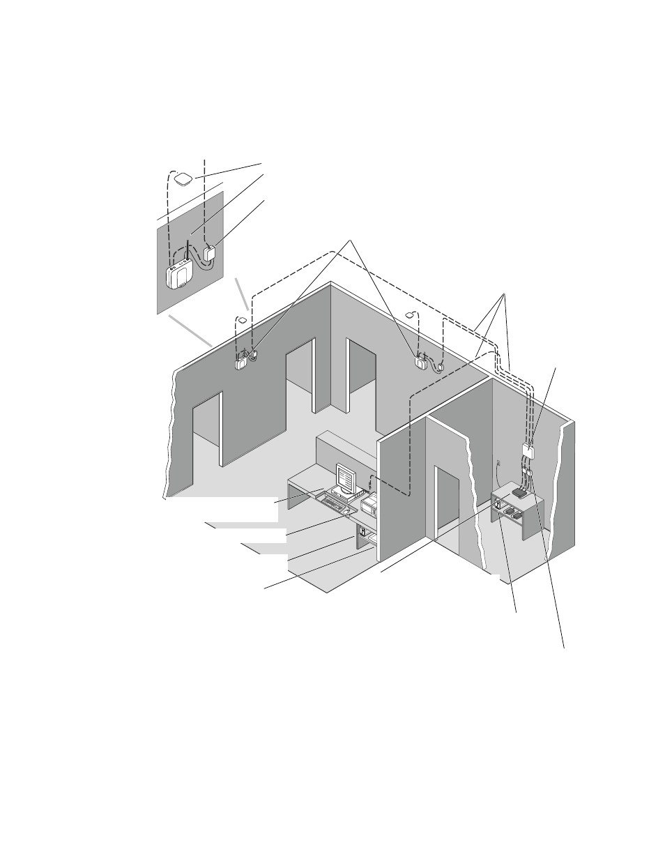
Plan equipment location
The following illustration shows typical locations for installation of wireless Acuity LT
System components.
Printer is located near the CPU.
Access points (APs) are mounted in hallways, seven inches from the
ceiling or above the ceiling.
UPS provides temporary power to
components at the nurses station.
Switch and network components
are typically located in an
equipment closet.
UPS provides temporary power to the switch
and network components.
Data cables are routed from the switch to the
APs and CPU, typically up through the wall and
overhead through ceiling access.
Modem connects to the CPU and to a dedicated analog
phone line to allow remote access for technical support.
Typical network
termination for
data cables.
Sandra “D” (SD) type antenna is mounted on the ceiling for best reception.
Whip-type antenna is mounted on the AP.
Power-over-ethernet (PoE) device separates out DC power from the data cable and
routes data and power to the AP.
Power-over-ethernet (PoE) devices
merge DC power for the AP into the
data cable, for ease in wiring.
Display(s) and CPU are on a
desk at the nurses station.
- GS 777 Wall Transformer - User Manual (1 page)
- 7114x Desk Charger - User Manual (8 pages)
- Mounting Bracket Replacement Kit for 7670-12 Mobile Stand with Mounting for 767XX and 777XX - User Manual (2 pages)
- 767 Diagnostic System - User Manual (136 pages)
- 767 Diagnostic System - User Manual (16 pages)
- 118 Series PanOptic Ophthalmoscope - User Manual (28 pages)
- 118 Series PanOptic Ophthalmoscope - User Manual (26 pages)
- VS100 Welch Allyn Vision Screener - User Manual (34 pages)
- SureSight Vision Screener - User Manual (36 pages)
- SureSight Vision Screener - User Manual (32 pages)
- Connex Integrated Wall System - User Manual (161 pages)
- SureSight Autorefractor - User Manual (36 pages)
- 12500 Binocular Indirect Ophthalmoscope Power Source - User Manual (12 pages)
- TM286 Auto Tymp - User Manual (72 pages)
- TM 262 Auto Tymp - User Manual (92 pages)
- MicroTymp 3 portable tympanometric instrument - User Manual (76 pages)
- Audioscope 3 Portable Screening Audiometer - User Manual (32 pages)
- AM282 Audiometer - User Manual (32 pages)
- AM 232 Manual Audiometer - User Manual (38 pages)
- Digital MacroView Otoscope - User Manual (32 pages)
- Digital MacroView Otoscope - User Manual (476 pages)
- OAE Hearing Screener - User Manual (62 pages)
- OAE Hearing Screener - User Manual (56 pages)
- OAE Data Manager - User Manual (39 pages)
- Ear Wash System 29350 - User Manual (28 pages)
- Standard laryngoscope blade assemblies - User Manual (6 pages)
- Standard laryngoscope handles - User Manual (6 pages)
- Rechargeable laryngoscope handles - User Manual (8 pages)
- Fiber optic laryngoscope handles - User Manual (7 pages)
- Fiber optic laryngoscope blade assemblies - User Manual (6 pages)
- Original Harvey and Harvey DLX Double and Triple Head Stethoscopes - User Manual (28 pages)
- Harvey Elite Stethoscope - User Manual (2 pages)
- Professional Stethoscope - User Manual (2 pages)
- EXPENDABLE ILLUMINATOR - User Manual (2 pages)
- KleenSpec Single Use Vaginal Speculum - User Manual (2 pages)
- KleenSpec Vaginal Specula Illumination System - User Manual (20 pages)
- KleenSpec 790 Series Cordless Illumination System - User Manual (32 pages)
- KleenSpec 790 Series Cordless Illumination System - User Manual (222 pages)
- Video Colposcope - User Manual (48 pages)
- Video Colposcope - User Manual (400 pages)
- Rigid Reusable & Single use Sigmoidoscopes, Anoscopes, Accessories - Cleaning, Disinfection, and Sterilization - User Manual (12 pages)
- 6V Power Supply, Rectal Light Handle - User Manual (240 pages)
- Fl-100 Intubating Fiberscope - User Manual (32 pages)
- EpiScope Skin Surface Microscope - User Manual (2 pages)
- 719 Series Lithium Ion Handle - User Manual (2 pages)