Connections, Connections 3, Connect the flexstat to the computer. (see – KMC Controls HTO-1103 User Manual
Page 3: Caution
HTO-1103 FlexStat Firmware Flash Upgrade Kit
3
Installation Guide, Rev. N
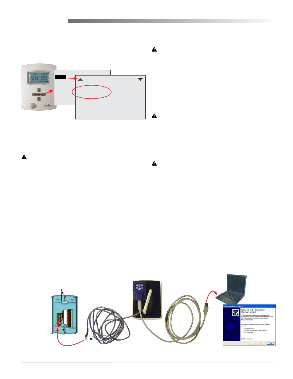
Connections
NOTE: A FlexStat’s existing firmware is displayed
in the FlexStat’s About menu. Before
making connections, check to see if the
latest firmware is already installed. (See
.)
Illustration 5—Make Kit Connections (BAC-10000 Series Shown)
3–5. Remove WD jumper
and attach adapter plate
and “pod” to back
1 & 2. Turn cover hex
screws CLOCKWISE
and remove cover
8. Connect
cable’s
two pins to
the power
terminals
(LAST)
6. Connect USB cable
between pod and PC
7. Install
drivers
4. Attach the appropriate adapter plate to the back
of the cover.
CAUTION
To prevent damage, never plug the programming
pod into a FlexStat that is powered. Always attach
the power cable last.
5. Attach the programming pod to the FlexStat’s
flash port. See
for the proper orien-
tation for the respective model. The BAC-13xxxx
and BAC-14xxxx CO
2
model ports require the
914-001-10 flash pod pin extender card.
CAUTION
To prevent damaging the FlexStat or programming
pod, be sure all the pins align properly with the
sockets!
6. Plug the USB cable into the pod and then the
other end into the USB port of the computer.
CAUTION
To prevent the possibility of damage caused by
a ground loop between the FlexStat transformer
and the computer power supply, using an optically
isolated USB hub or using a laptop operating on
batteries only is recommended.
7. When the Found New Hardware Wizard pops up
on the screen, let it install the required drivers.
8. After the Wizard is finished, remove the protec-
tive rubber cap and insert the power adaptor
cable’s two pins into the power section of the
wall-mounted terminal blocks. See
for the proper terminals for the respective model.
(Keep the cap on the pins when not in use.)
9. Use the Firmware Upgrade Tool to update the
firmware. (See
Updating the Firmware on page 5
Illustration 4—Check Current Firmware Version
1. Turn the hex screws in the bottom and top of the
FlexStat CLOCKWISE (only) until they clear the
cover. (See
.)
CAUTION
To prevent mounting screw heads from touching
the circuit board in the thermostat, use only the
mounting screws supplied by KMC Controls. Do not
turn the screw in farther than necessary to remove
the cover.
2. Carefully pull the cover away from the wall-
mounted backplate (mounting base).
3. Temporarily remove—but do not discard—the
WD (watchdog) jumper (from the two pins clos-
est to the center of the board—see
). To avoid losing the jumper, temporar-
ily put the jumper on one pin only.
NOTE: To replace a lost WD jumper, use a standard
2.54 mm computer jumper sourced locally. A
KMC HPO-0063 jumper can also be used if
the finger tab is cut off to clear the backplate.
MAIN MENU
ABOUT
ADVANCED
ALARM
DATE/TIME
SCHEDULE
SETPOINTS
SYSTEM
ABOUT FLEXSTAT
MODEL: BAC–11163C
FW: FLEXSTAT
R2.0.0.12
APP: AIR HANDLER
OPT: MOD H / MOD C
MORE