EFCO S5500 SSG Captured User Manual
Page 54
EFCO CORPORATION 6/2012
PART NO. Y556
Page 54 of 81
S-5500 SSG and Captured Corner Mullion Installation Instructions
Section IX: Vertical Splice Joints
Installation for Captured System
STEP #1 LOCATE SPLICE JOINTS
A. Splice joints should occur at spandrel areas (if possible). Refer to the approved shop
drawings for actual locations.
B. The mullion splice must be field assembled in the top of the lower mullion after the corner
frames have been set into the opening and anchored at the sill.
C. GENERAL NOTE: The following pages depict a splice joint of 1/2”. This will allow plus or
minus 1/4” of movement for each splice location. Thermal expansion and live deflection
requirements should be considered when determining the location and quantities of
splice joints. If the total amount of movement cannot be accommodated by locating
splices at every other floor, or alternately, at each floor, expansion horizontals or some
alternative method should be used. Contact EFCO for further evaluation.
D. Refer to this section for pressure plate and cover splice locations, mullion splice locations,
and sealing instructions.
E. Once a final check of the expansion joint placement and mullion position is made, final
match drilling of the mullion through the anchor holes may be completed.
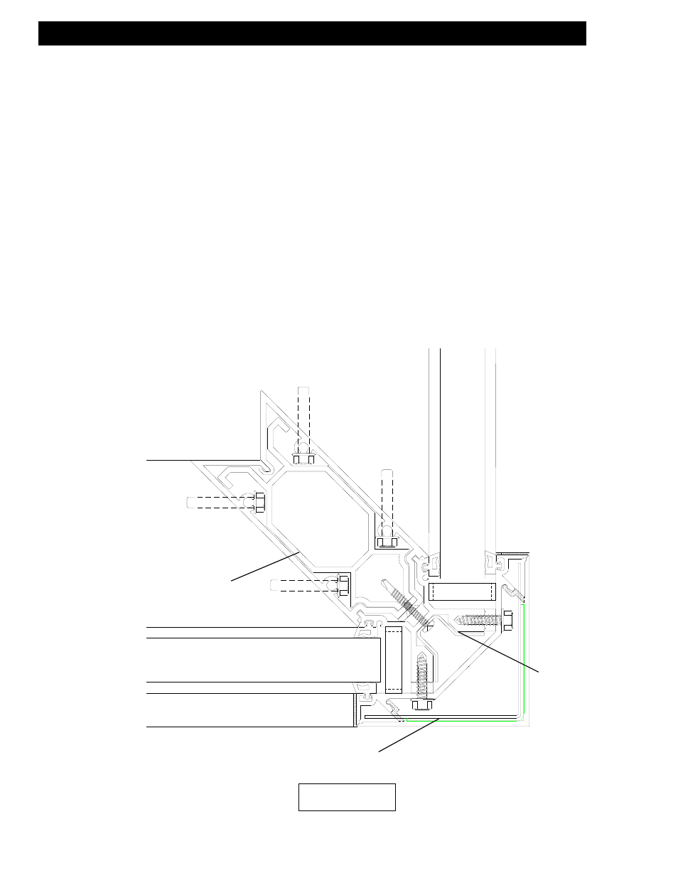
Mullion splice sleeve with
bond breaker tape
Cover splice sleeve with
bond breaker tape
Mullion adapter
splice sleeve
with bond
breaker tape
PLAN VIEW