Dynalco AF-900PC Air/Fuel Ratio Controller User Manual
Page 35
34
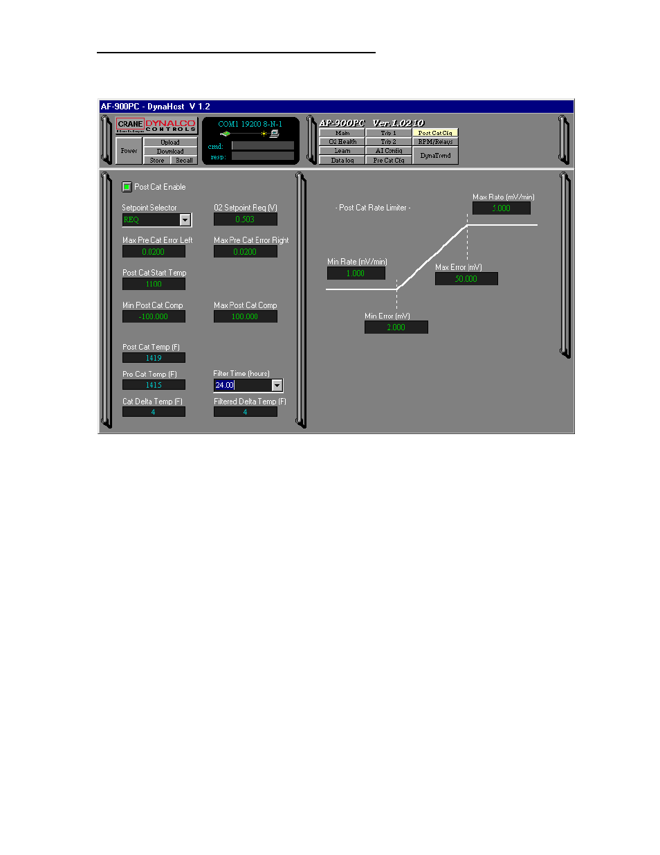
POST-CATALYST CONFIGURATION SCREEN
This screen (Fig. 16) sets up the post-catalyst system. All parameters that are
green may be changed.
Post-Catalyst Configuration Screen
Figure 16
Post-Cat Enable: This button allows the post-catalyst control to be enabled and
disabled.
Setpoint Selector: Selects the source for the final post-cat sensor target voltage.
When set to REQ, the final target voltage will be the O
2
Setpoint Req (V) voltage.
When set to MAP, the final target voltage becomes the O
2
Setpoint Req (V)
modified by the MAP table.
O
2
Setpoint Req (V): Sets the initial target voltage for the post-cat O
2
sensor.
Typical range for this parameter is 0.650 to 0.850 V.
Max Pre-Cat Error Left: Sets the maximum allowable left bank pre-cat error for
the post-cat control to be active. Post-cat integration is frozen when the error
exceeds this value. Typically set to 0.020
Max Pre-Cat Error Right: Sets the maximum allowable right bank pre-cat error for
the post-cat control to be active. Post-cat integration is frozen when the error
exceeds this value. Typically set to 0.020.
Post-Cat Start Temp: Sets the minimum catalytic converter outlet temperature to
enable post-catalyst control. This temperature should be set high enough to allow
proper catalytic converter action before post-catalyst control is attempted.