Mounting the sensors, Mounting an ultrasonic sensor, Mounting a doppler velocity sensor – ADS Environmental Services Model 3600 530002 A2 User Manual
Page 46: Ring, sensor, and special installations 4-13
Ring, Sensor, and Special Installations
4-13
Mounting the Sensors
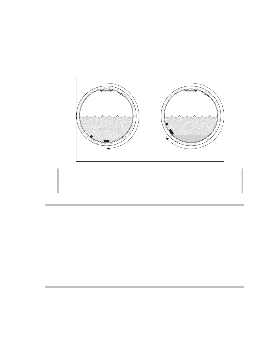
The following topics guide you through the steps necessary to mount the ultrasonic,
velocity, and pressure sensors. The following figure illustrates their positions on the
ring.
Crank
180
°
With Silt
Without Silt
Ultrasonic
Depth
Crank
Ultrasonic
Depth
Pressure
Velocity
180
°
+ ?
°
Depth
Velocity
0
°
0
°
Sensor Positions
Note:
When mounting the sensors, check on the site report to see if silt is
present. If silt is present, this will affect the sensor placement on the ring.
Refer to 4-18 for more information on silt deposits.
Mounting an Ultrasonic Sensor
Mount the ultrasonic sensor to the inside of the ring.
l
Slide the base of the sensor into the sensor mount (located at the top of the
ring). The top of the sensor (with the four disk-shaped transducers) should
face downwards towards the surface of the water.
l
Verify that the ultrasonic sensor is mounted on the ring at the pipe’s crown
(soffit). Later, when installing the ring and sensor into the pipe, you will have
to verify that the ultrasonic sensor is both horizontally and vertically level with
the surface of the flow.
Mounting a Doppler Velocity Sensor
l
Mount the velocity sensor to the inside of the ring with two M-3
×
10 mm
stainless steel screws. This sensor should be placed below and perpendicular
to the ultrasonic sensor. Do not substitute any other screws.