Great Plains PTO Kits 2-3-Section User Manual
Page 85
Great Plains Manufacturing, Inc.
Appendix A - Installation
81
2014-09-10
411-015M
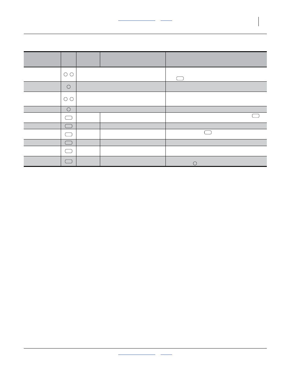
Hydraulic
Connections
Call-
out
Part
Hose Description
Comments
Fan Pressure hose
from hitch
,
Existing Hose(s)
Remove hose handles. Disconnect from fan. Reconnect
hitch end to PTO pump outlet. Reconnect fan end to new
hose
.
Fan Case Drain
hose
Existing Hose(s)
Remove QD fittings at hitch end. Connect hitch end to
reservoir case drain inlet.
Fan Return hose
from hitch
,
Existing Hose(s)
Remove hose handles. Disconnect from fan. Reconnect
hitch end to reservoir inlet. Reconnect rear end to cooler
outlet.
Fan Bypass Loop
Existing hose
Left in place.
Flow Control Return
hose
841-518C
HH1/2R2 054 7/8FJIC
Connect flow control valve Port T to the new tee
at
fan
Pump Supply Hose
841-920C
HH1 1/4R4 070 1 5/8FJIC
Connect reservoir outlet to pump inlet.
Fan Return to
Cooler hose
841-921C
HH5/8R2 032 7/8FJIC
Connect the new tee
at the fan outlet to the cooler
inlet.
Fan Return Tee
851-311C
TE 7/8MJIC 7/8MJIC 7/8FJIC
Add to existing elbow at fan outlet.
Fan Supply hose
851-345C
HH5/8R2 060 7/8FJIC
Connect flow control valve Port M to the existing elbow
at the fan motor inlet.
Fan Supply Hose
851-346C
HH5/8R2 045 7/8FJIC
7/8MJIC
Connect flow control valve Port P to the existing fan
pressure hose
(fan end).
A
B
297
C
D
E
L
274
295
282
283
295
295
296
297
B