Install 8-inch fan cooler, 8in: dismount screen assembly, 8in: remove screen cap and rain cover – Great Plains PTO Kits 2-3-Section User Manual
Page 40: 8in: dismount sensor, 8in: dismount fan screen, 8in: break down cooler assembly, 8in: install screen and shroud, 8in: install sensor bracket, 8in: adjust sensor gap
36
2- & 3-Section YP PTO Pumps
Great Plains Manufacturing, Inc.
411-015M
2014-09-10
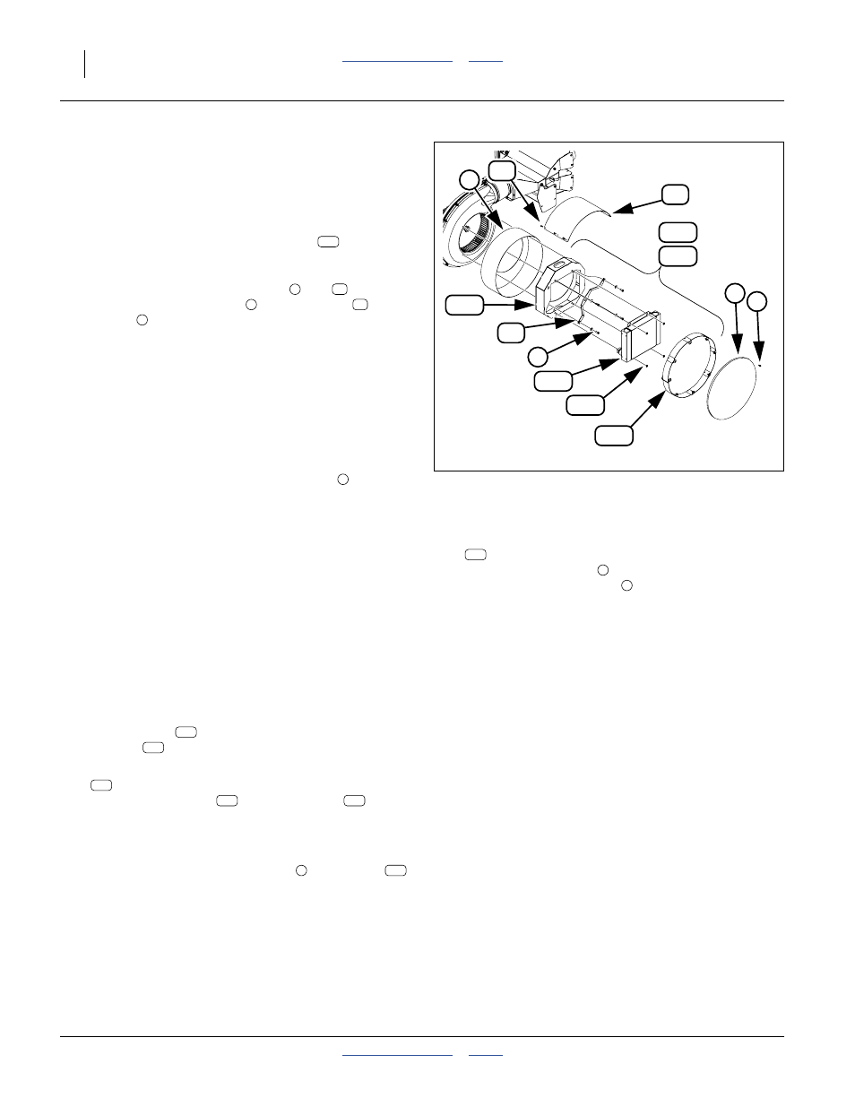
Install 8-Inch Fan Cooler
This page applies only to 8-inch/4-cage-screw fans.
For 6-inch fans, see page 32.
8in: Dismount Screen Assembly
Refer to Figure 40 (the fan screen extension
is not
present at dismount and is added at step 66 on page 38)
8in: Remove Screen Cap and Rain Cover
47. Remove and save all fasteners (
and
shown) securing the cap
and rain cover
to the
screen
.
Note: The cap and cover screws are different sizes.
48. Remove and save the screen cap, rain cover and
screws.
8in: Dismount Sensor
Note which two holes are used for the sensor bracket,
and which two only for the fan screen.
49. Disconnect the sensor lead outside the fan screen.
50. Remove and save two sets of fasteners
securing
the sensor bracket to the fan housing.
51. Remove and save the sensor assembly.
8in: Dismount Fan Screen
Note: The fan housing and fan screen are eccentric in
shape. Although the four mounting holes may line
up in various orientations of the screen, only one
orientation is correct.
52. Make an alignment mark on the fan screen and on
the fan housing, to indicate factory alignment. Or
take a photograph for reference.
53. Loosen or remove the last two sets of fasteners
securing the fan screen to the fan housing.
8in: Break Down Cooler Assembly
Note: The shroud
cannot be installed with the
cooler
mounted.
54. Remove and save four sets of:
803-043C NUT HEX WHIZ 5/16-18 PLT
Separate the cooler
from the shroud
.
8in: Install Screen and Shroud
Note: It may be easier to use two saved screws, without
washers, at the sensor bracket locations to
temporarily hold the fan screen
and shroud
in place while seated the screws and washers at
the other two fan housing holes.
55. Select the shroud:
401-958H 8IN FAN HYD OIL COOLER
the saved fan screen
and
two sets saved fasteners
.
Align the fan screen as marked or shown in your
photo. Place the shroud inside the screen, with the
cutaway corner on the bottom and facing away from
the fan outlet. Loosely secure both to the fan
housing using the saved fasteners.
8in: Install Sensor Bracket
56. Re-install the sensor bracket using two sets of
saved fasteners. Fully tighten all four sets of
fasteners securing the screen and bracket to the fan
housing.
8in: Adjust Sensor Gap
Note: The re-installed sensor is now further away from
the fan hub than prior to kit installation. The
sensor gap must be reset.
57. Loosen the jam nuts on the sensor. Check for axial
play on the fan hub; if there is any, pull the hub
toward the sensor. Screw the sensor toward the hub
until contact. Back off one turn. Check clearance.
Secure jam nuts.
128
127
4
210
223
136
53
1
Figure 40:
8 in. Fan Cooler Arrangement
36377
1
27
53
4
136
223
210
223
136
136
136
4