8in: modify fan cage, 8in: install cooler, 8in: install screen extension – Great Plains PTO Kits 2-3-Section User Manual
Page 42: 8in: install screen cap, Step 66
38
2- & 3-Section YP PTO Pumps
Great Plains Manufacturing, Inc.
411-015M
2014-09-10
8in: Modify Fan Cage
Refer to Figure 43
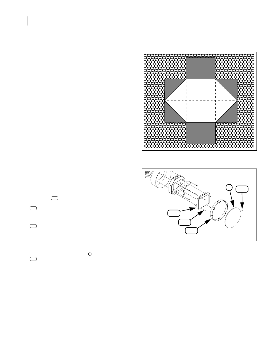
63. Prepare an exit opening in the fan cage for the
cooler hoses. The hole needs to be:
Note: If an existing rpm sensor lead hole is present, and
at a suitable location, enlarge it for hose use.
8in: Install Cooler
64. Route the cooler hoses through the hole prepared
Refer to Figure 44
65. With the elbows toward the cooler shroud, position
the cooler
on the threaded studs of the cooler
shroud. Secure with 4 whiz nuts:
803-043C NUT HEX WHIZ 5/16-18 PLT
8in: Install Screen Extension
66. Select one new:
421-615D CRARY 8IN FAN SCREEN EXT
and eight saved screws originally used to secure
the screen cap to the screen. Secure the extension
to the screen using the saved screws.
8in: Install Screen Cap
67. Select the saved screen cap
and eight new:
Secure the cap to the screen extension by creating
new holes from the face of the screen.
• located at bottom center of the fan cage,
• on the center-line of the MJIC elbow ports,
• wide enough for a 3/4 FJIC hose fitting, about:
3.2 cm (1
1
⁄
4
inches)
a
• long enough for one hose diameter plus one
3/4 FJIC or 7/8 FJIC hose fitting, about
5.7 cm (2
1
⁄
4
inches)
total, and
• have a smooth edge. Making cuts (- - -) as
shown, and folding back the cage edges, to the
inside, provides an adequately smooth edge.
a. For assembly 401-143L, with 7/8 JIC hose ends, use
3.8 cm (1
1
⁄
2
inches) wide, 6.4 cm (2
1
⁄
2
inches) long
Figure 43:
8in: Hose Opening in Cage
210
223
Figure 44:
8 in. Fan Cooler Install
36377
223
210