6in: install fan cooler(s), 6in: install cooler, Inch fan: break down cooler assembly – Great Plains PTO Kits 2-3-Section User Manual
Page 37: 6in: install cooler shroud
Great Plains Manufacturing, Inc.
Appendix A - Installation
33
2014-09-10
411-015M
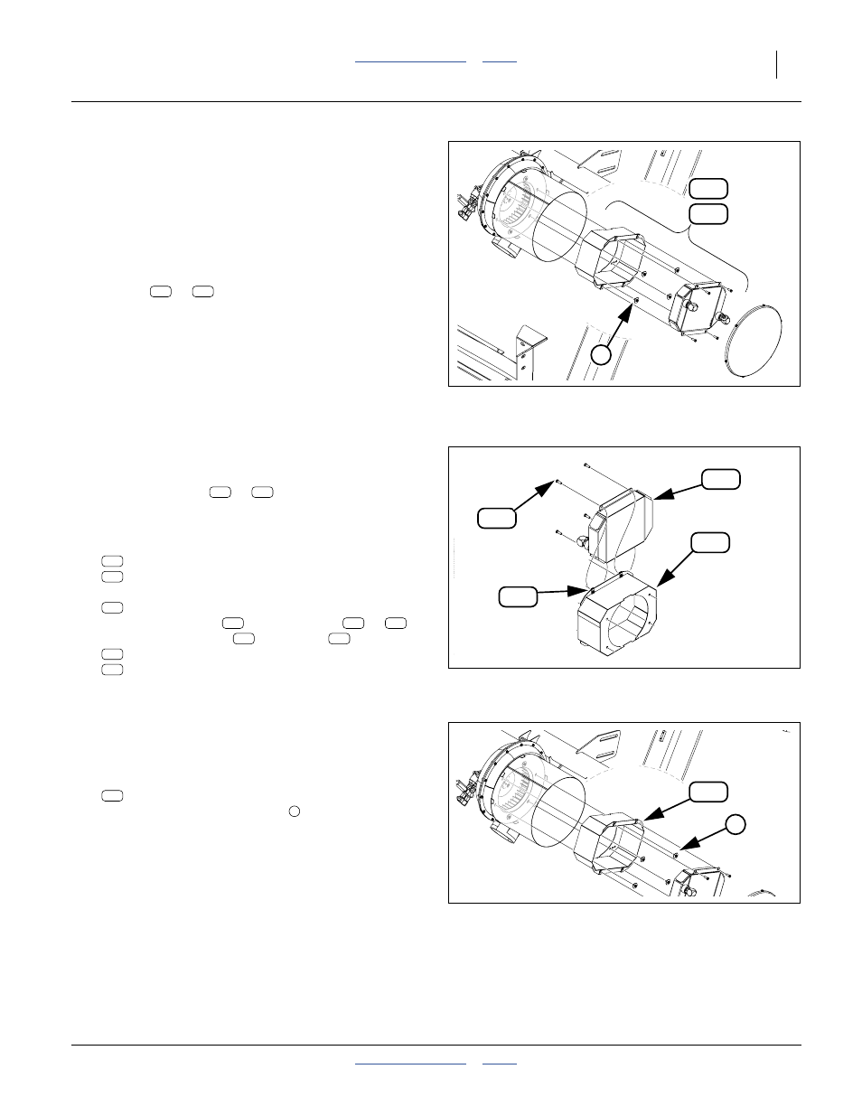
6in: Install Fan Cooler(s)
This page applies only to 6-inch/6-cage-screw fans.
For 8-inch fans, continue page 36.
Refer to Figure 32
In normal use, the hydraulic fan circuit requires enough
power that, absent a tractor oil radiator or local cooler,
the oil would overheat. The Yield-Pro
®
PTO pump kit
includes one or more cooler (radiator)
assemblies (
or
) that install inside the fan
cage(s).
Note: Do not disconnect the fan motor hoses during
cooler installation. Those hoses are reconnected
during “Install Hoses” on page 49.
6in: Install Cooler
6-Inch Fan: Break Down Cooler Assembly
Refer to Figure 33
The cooler assembly (
or
) must be partially
disassembled to have access to the shroud mounting
holes.
35. Select one new of:
401-143L 6IN HYD FAN COOLER 7/8MJIC
401-833L 6IN HYD FAN COOLER ASSY
Remove and save four:
802-159C HHCS 5/16-18X1 GR5
Leave the nut clips
on the shroud (
or
).
Separate the shroud
and cooler
:
401-834H 6 IN HYD FAN SHROUD
810-804C C12 HYD OIL COOLER
6in: Install Cooler Shroud
Refer to Figure 34 (shown with fan cage dismounted for
clarity of bolt hole assignment - the cage should already be
secured via top and bottom holes)
36. Select one of new:
401-834H 6 IN HYD FAN SHROUD
and four sets saved fasteners
.
Attach the shroud through the fan cage holes, to the
fan housing, using the saved fasteners.
125
124
4
Figure 32:
6 in. Fan Cooler Arrangement
36376
124
125
126
201
221
192
Figure 33:
Break Down Cooler
34632
124
125
124
125
201
192
126
136
126
221
126
221
Figure 34:
Install Cooler Shroud
36376
4
126
126
4