Valve on fan manifold, Valve under rear walkboard – Great Plains PTO Kits 2-3-Section User Manual
Page 49
Great Plains Manufacturing, Inc.
Appendix A - Installation
45
2014-09-10
411-015M
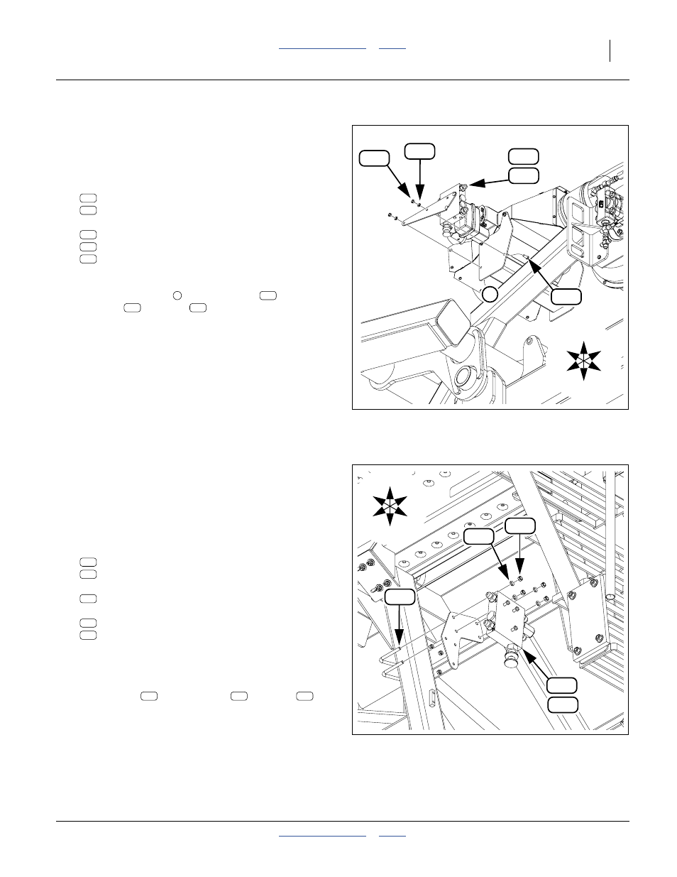
Valve on Fan Manifold
This location applies to kits 401-935A and 401-937A, for
models YP1225A and YP1625A. For other kits/models,
see the page director table on page 43.
Refer to Figure 54
84. Select one of new:
401-977L YP12A,16A GRND DRV FLOW CNTRL
411-003S YP12A,16A PTO CNTRL VALVE ASSY
and two sets new:
802-017C HHCS 3/8-16X1 GR5
804-013C WASHER LOCK SPRING 3/8 PLT
803-014C NUT HEX 3/8-16 PLT
With the knob down and the valve to font on the
mount, secure the valve assembly to the right hand
manifold end plate
, lock
washers
and nuts
.
Continue at “Install Hoses” on page 49.
Valve Under Rear Walkboard
This location applies to kits 401-938A and 411-147A, on
models YP1630F and 1625AHD. For other kits/models,
see the page director table on page 43.
Refer to Figure 55 (the valve assembly is shown exploded for
clarity - the valve and mount plate are pre-assembled)
85. Select one of new:
401-978L YP1630F PTO FLOW MNT ASSY
411-142L YP16AHD PTO FLOW CONTROL
two new:
806-138C U-BOLT 3/8-16 X 4 1/32 X 3 3/4
and four sets new:
804-013C WASHER LOCK SPRING 3/8 PLT
803-014C NUT HEX 3/8-16 PLT
With the valve assembly knob down, position the
mount plate on the inside and as high as possible
on the left walkboard vertical support tube. Secure
with U-bolts
, lock washers
and nuts
.
Continue at “Install Hoses” on page 49.
195
153
214
U
D
B
F
L
R
173
208
1
Figure 54:
Valve Installation at Manifold
36398
153
173
195
214
208
1
195
214
208
220
154
214
208
176
U
D
L
R
F
B
Figure 55:
Rear Walkboard Valve Installation
36391
154
176
220
214
208
220
214
208