6in: relocate sensor bracket, 17 b a, Ba 17 – Great Plains PTO Kits 2-3-Section User Manual
Page 36
32
2- & 3-Section YP PTO Pumps
Great Plains Manufacturing, Inc.
411-015M
2014-09-10
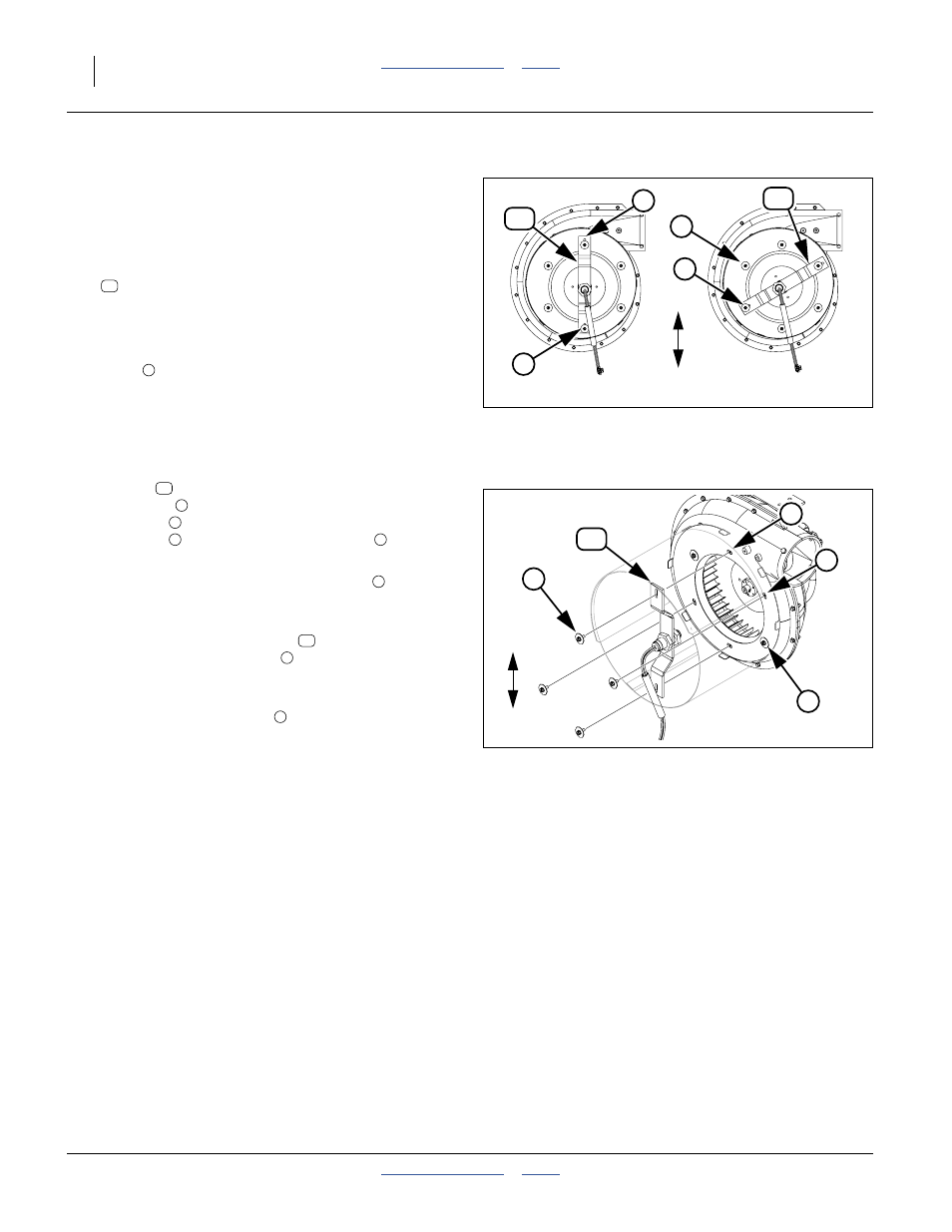
6in: Relocate Sensor Bracket
This page applies only to 6-inch/6-cage-screw fans.
For 8-inch fans, continue page 36.
Refer to Figure 30 (top and bottom are relative to Up and
Down, and not to the fan exit port, often not at top)
30. Inspect the fan cage for presence of a:
401-537D DJ FAN SENSOR MOUNT BRKT
The bracket may or may not have a sensor installed.
If there is no sensor bracket, skip to step 33.
If the bracket is installed in the top and bottom
holes
, skip to step 33.
If the bracket is not in the top-most and bottom-most
holes, it must be relocated.
Refer to Figure 31 (top and bottom are relative to Up and
Down, and not to the fan exit port, often not at top)
31. This step presumes that there is a sensor
bracket
, and it is mounted in one of the lateral
holes sets
. Remove and save two sets of
fasteners
securing the bracket, and two sets of
fasteners
at the top and bottom holes
, four sets
total.
Note: Leave the final set of lateral fasteners
in place,
so that the fan cage does not need to be
re-mounted.
32. Relocate the sensor bracket
to a vertical
orientation, using hole set
. Secure it with two sets
of saved fasteners.
33. Remove and save the four or remaining two sets of
fasteners at lateral holes
. These holes are used
for mounting the cooler in the following steps.
34. Repeat step 28 through step 33 for all hydraulic fans
on the planter.
Continue at “6in: Install Fan Cooler(s)” on page 33
17
b
a
U
D
b
a
17
OK
Relocate
Figure 30:
Inspect Sensor Bracket
36004
17
a
17
b
a
U
D
4
5
Figure 31:
Relocate Sensor Bracket
36005
17
b
4
4
a
5
17
a
5