Great Plains PTO Kits 2-3-Section User Manual
Page 71
Great Plains Manufacturing, Inc.
Appendix A - Installation
67
2014-09-10
411-015M
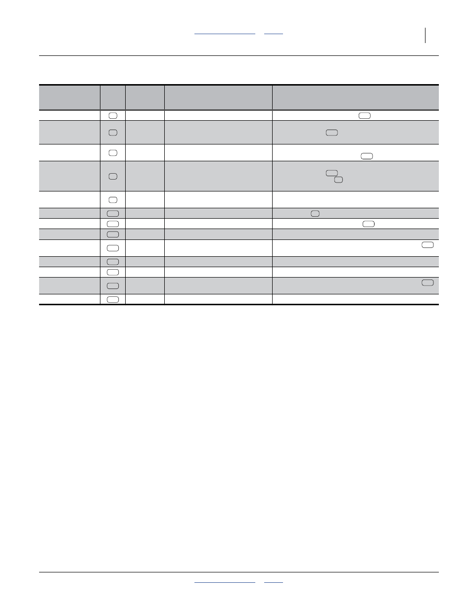
Hydraulic
Connections
Call-
out
Part
Hose Description
Comments
Fan Return Tee
811-080C
TE 3/4MJIC 3/4MORB 3/4MJIC
Remove. Replace with cross
.
Fan Case Drain
811-812C
HH1/4R2 228 9/16FJIC
Disconnect from tee at steering control valve block.
Replace with cap
at tee. Re-connect hitch end to
reservoir case drain inlet.
Fan Return
Re-connect hitch end to flow control valve Port T. Re-
connect fan end to new cross
at fan return.
Fan Return
841-459C
HH1/4R2 162 9/16FJIC
Disconnect from tee at steering control valve block.
Replace with cap
at tee.
Disconnect from tee
at fan return.
Hose is not reused.
Fan Pressure
841-460C
HH1/2R2 174 3/4MORB
3/4FJIC90
Remove hitch handles and fittings up to hose MORB.
Re-connect hitch end to valve port M.
Fan return
811-147C
CR 3/4MJIC
Replace tee
at fan motor return.
Cooler Inlet hose
811-268C
HH1/2R2 048 3/4FJIC
Connect from fan return cross
to cooler inlet.
Cooler Outlet
811-268C
HH1/2R2 048 3/4FJIC
Connect from cooler outlet to reservoir return inlet.
Pump Output
811-488C
AD 3/4FORB 3/4FORB
Remove this adaptor from the new pump assembly
.
Relocate to valve port M.
Steering drain
841-273C
CP 3/4FJIC
Cap for hose removed at steering control valve.
Steering return
841-273C
CP 3/4FJIC
Cap for hose removed at steering control valve.
Pump Output
841-919C
AD 7/8FJIC 3/4MORB
Remove this adaptor from the new pump assembly
.
Relocate to valve port M.
PTO Pump Inlet
841-985C
HH1 1/4R4 120 1 5/8FJIC
Connect from reservoir outlet to pump inlet.
42
235
49
265
235
65
255
42
66
235
41
240
235
240
249
130
265
265
281
130
291