Install the hydraulic lift cylinders – Wheatheart X160 Series User Manual
Page 42
3. A
SSEMBLY
W
HEATHEART
- G
RAIN
A
UGERS
X160-85, X160-105, X160-125
42
30875 R0
3.2.3. I
NSTALL
THE
H
YDRAULIC
L
IFT
C
YLINDERS
• See “Install the X160-85 Hydraulic Lift Cylinders” below for information on
installing hydraulic lift cylinders on X160-85 augers.
• See “Install the X160-105/125 Hydraulic Lift Cylinders” on page 44 for
information on installing hydraulic lift cylinders on X160-105/125 augers.
I
NSTALL
THE
X160-85 H
YDRAULIC
L
IFT
C
YLINDERS
1. Identify the tube section where the hydraulic lift cylinders install, and note the
location of the cylinder mounts.
2. Slide the cylinder rod guide onto the end of the track closest to where the lift
cylinders install. Ensure that gussets of ram guide are facing the discharge
end.
Note:
The hydraulic lift cylinders must be positioned with the rod end towards the
discharge end of auger.
Important:
Always use a fork lift to lift hydraulic cylinders during installation.
3. Use a sling around all 3 cylinders, and align cylinders to tube, as shown. Lift
up hydraulic cylinders to position, and fasten hydraulic cylinders to cylinder
attach brackets and back-arm bracket with eight 3/4” x 2” GR5 bolts and
locknuts.
Note:
4. Slide the cylinder rod guide toward the lift cylinders until the rod ends pass
through the three holes provided on the cylinder rod guide, and then insert a
5/16” x 2” roll pin into the hole on the end of each cylinder rod to prevent
separation of rods and cylinder arm guide.
5. Ensure all bolts are fully tight.
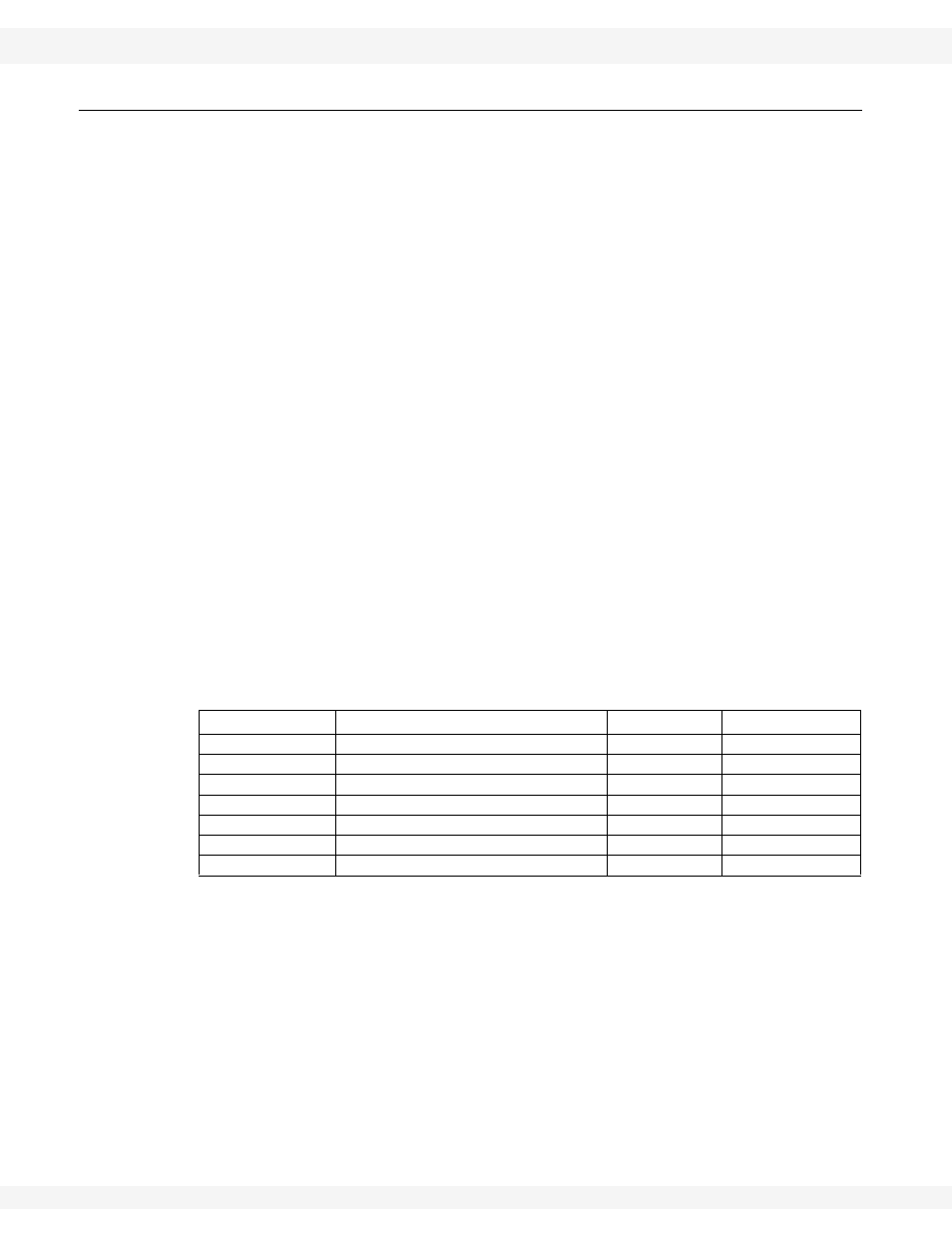
Table 3.3 Install the X160-85 Hydraulic Lift Cylinders
Diagram #
Description
Part #
Quantity
1
Back-arm bracket
n/a
1
2
Cylinder-mount bracket
n/a
1
3
Hydraulic cylinder assembly
20733
1
4
Cylinder rod guide
20707
1
5
3/4” x 2” bolts
19592
8
6
3/4” nuts
19601
8
7
5/16” x 2” roll pin
18079
3