Connect auger tubes – Wheatheart X160 Series User Manual
Page 40
3. A
SSEMBLY
W
HEATHEART
- G
RAIN
A
UGERS
X160-85, X160-105, X160-125
40
30875 R0
3.2.2. C
ONNECT
A
UGER
T
UBES
Important:
Always strap tubes to the support stands to prevent the tubes from rolling off the
stands.
Note:
Assemble the auger tube starting with the discharge section and working toward
the intake section.
1. Bolt tube sections together (see Figure 3.5 for details), working from the
spout end (upper tube) toward the discharge end (lower tube):
a. Align flightings to ensure a continual spiral of auger surface, and connect
flight shafts with 5/8” x 4-1/2” bolts and 5/8” locknuts.
b. As flight shafts are connected, slide tube sections together and secure with
eleven 5/8” x 1-1/2” GR8 bolts and 5/8” locknuts. Use three 5/8” x 3” GR8
bolts and locknuts for the flange section where the two sections of tube
track meet (see Figure 3.4), or a single 5/8” x 2-1/2” GR8 bolt where tube
track meets a flanged section without a tube track (see Figure 3.5).
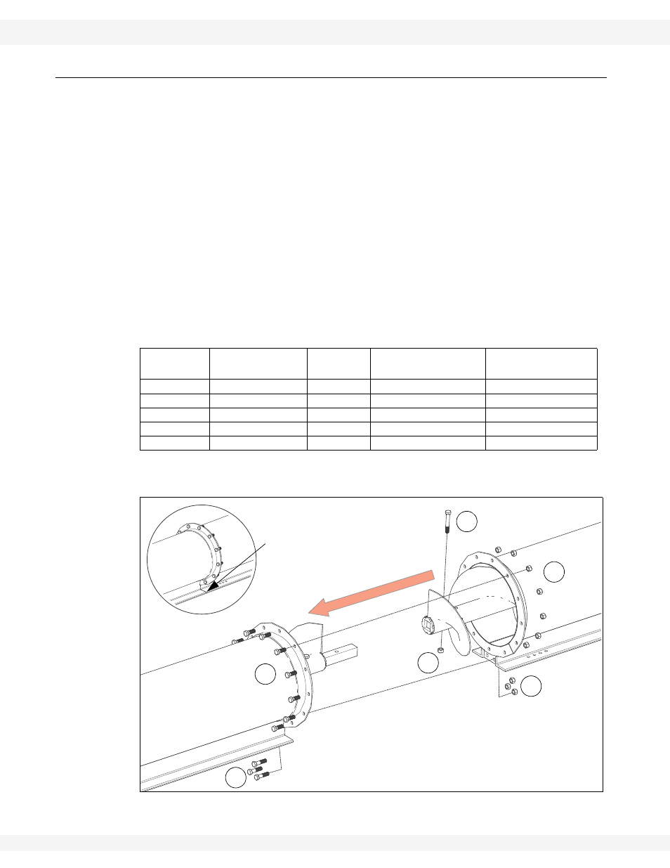
Figure 3.4 Track-to-Track Tube Section Connections
Table 3.2 Connecting Auger Tube Sections and Flights
Diagram #
Description
Part #
Tube Connection
(Track-to-Track)
Tube Connection
(Track-to-Flange)
1
5/8” x 4-1/2” bolt
18545
1
1
2
5/8” x 1-1/2” bolt
19590
11
11
3
5/8” x 3” bolt
21463
3
0
4
5/8” x 2-1/2” bolt
27589
0
1
5
5/8” nut
19600
15
13
1
2
3
5
5
5
USE A STRAIGHT-EDGE
TO ALIGN TRACKS TO ENSURE
A SMOOTH PATH FOR THE
TRACK SHOE