Wheatheart X160 Series User Manual
Page 102
3. A
SSEMBLY
W
HEATHEART
- G
RAIN
A
UGERS
X160-85, X160-105, X160-125
102
30875 R0
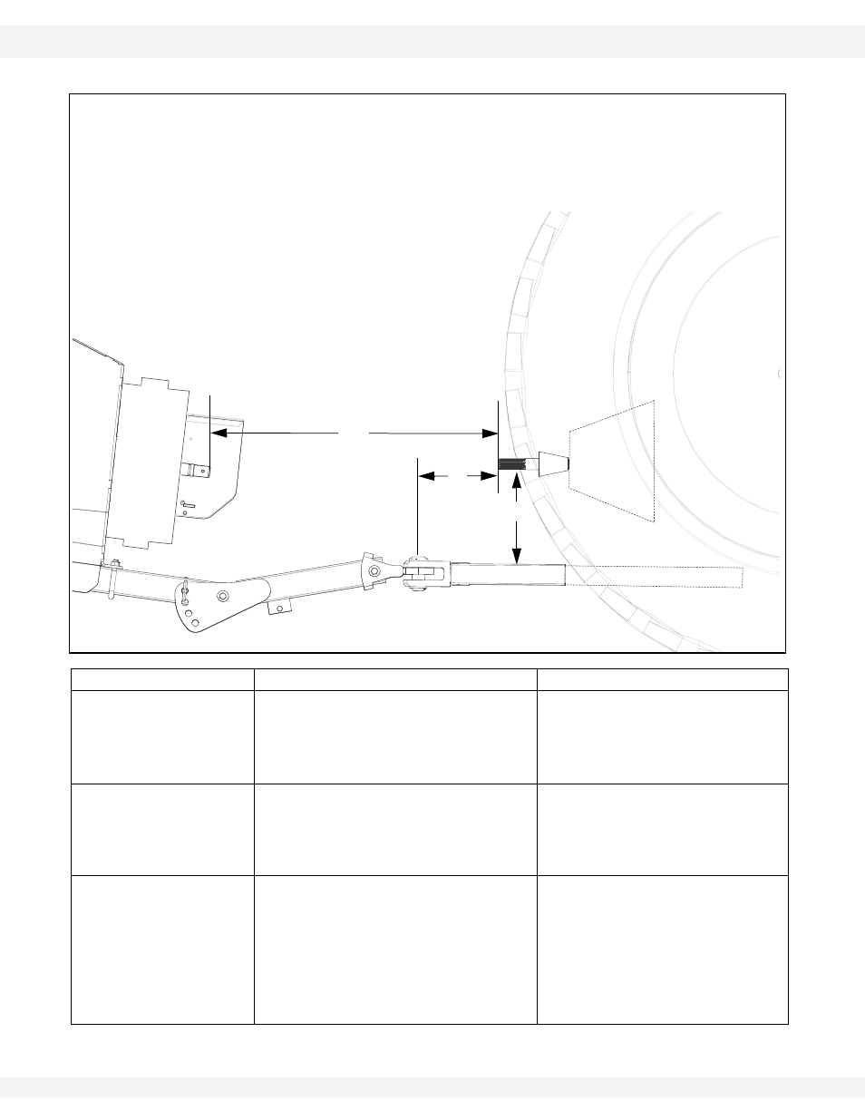
Figure 3.56 Measurements Between Drawbar and PTO Driveline
MEASUREMENT
PROBLEM
SOLUTION
If (A) is less than
14” (35.6 cm) (C) will
be less than the rec-
ommended 46”
(116.8 cm)
The PTO driveline will bottom out
when auger is in raised position.
• This will cause damage to the
PTO driveline, the bearing, or the
boot housing.
Pull out or lengthen the tractor
drawbar as needed to make (C)
46” (116.8 cm) when the auger
is in full down position.
If (A) is more than 14”
(35.6 cm) (C) may be
more than the recom-
mended 46”
(116.8 cm)
The PTO driveline will separate from
the auger in the lowered position.
• This will cause damage to equip-
ment and/or injury to personnel.
Shorten distance (C) to the rec-
ommended 46” (116.8 cm) by
attaching hitch to tractor draw-
bar at a point closer to the trac-
tor PTO shaft.
If (B) is more than
14” (35.6 cm) (C)
(between tractor PTO
shaft and auger input
shaft) shortens more
quickly when auger is
being raised
The u-joint angle on the PTO drive-
line will be too severe in the raised
position.
The PTO driveline will bottom out
before auger is fully raised.
• This will cause damage to the
PTO driveline, flight shaft, bear-
ing, and boot.
Raise the tractor drawbar until
dimension (B) is within the rec-
ommended 10” to 14”
(25.4 cm - 35.6 cm).
A………………………………14” (35.6 cm)
B………………………………10”- 14” (25.4 cm - 35.6 cm)
C………………………………46” (116.8 cm)
(MUST BE TAKEN WITH AUGER ON LEVEL GROUND
AND IN FULL DOWN POSITION) RAISE TRACTOR
DRAWBAR IF NECESSARY TO MAINTAIN (B) DIMENSION
OF 10” - 14” (25.4 cm - 35.6 cm)
C
A
B