Blade switching and direct connect backpacks, Figure 27, R4300 daisy-chain cabling example – ClearCube R Series Pentium 4 User Manual
Page 70
60 • Cage and Blade Installation
ClearCube Product Manual and Installation Guide
NOTE: Connecting a network cable to a C/Port jack on the Cage, or a C/Port cable to
a Network jack, will not damage the unit, but the system will not operate
correctly. This is a common installation error and should be one of the first
things checked when troubleshooting a problem with a system’s operation.
Blade Switching and Direct Connect BackPacks
To connect cables to a Blade Switching BackPack-equipped Cage, do the following:
1. Label, identify, or use different color cables to discriminate between desktop and
network wiring. For example, use grey for the network cables and blue for the
ClearCube desktop cables.
2. Connect eight C/Port cables from the Cage ports marked C/PORT to the patch
panel going to your desktops. Skip this step if installing I/Ports.
3. Connect eight network cables from the Cage ports marked ETHERNET to your
Ethernet network hub or switch.
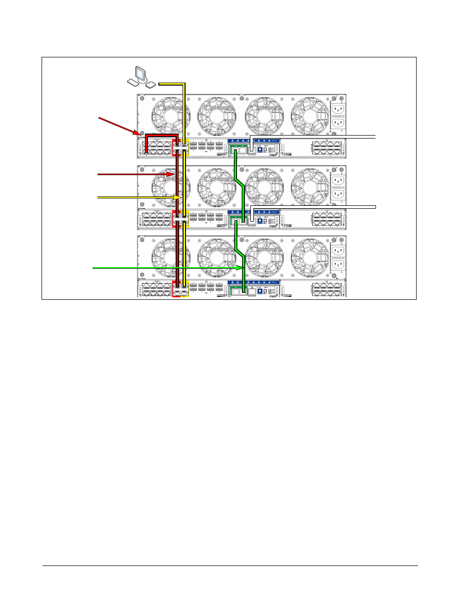
4. Connect the CONTROL IN port on the primary Cage (the Cage with the primary
RMC) to your network switch. Daisy-chain the CONTROL OUT port on the
primary Cage to the next Cage’s CONTROL IN port using the green daisy-chain
cable. Continue this daisy chain to connect all Cages in the rack.
Figure 27 R4300 Daisy-Chain Cabling Example
Admin C/Port
CLEARCUBE
Spare
Primary Cage
To Network
Secondary Cage
Tertiary Cage
with E-net Control Link
Admin
Daisy Chain
Control
Chain
Configuration
Cable
To Network
with E-net Control Link
No E-net Control Link
Spare
Daisy Chain
Admin
Daisy Chain
Admin C/Port
and Terminal