Figure 21, R4300 module bays, Figure 22 – ClearCube R Series Pentium 4 User Manual
Page 60: R4300 modules
50 • Cage and Blade Installation
ClearCube Product Manual and Installation Guide
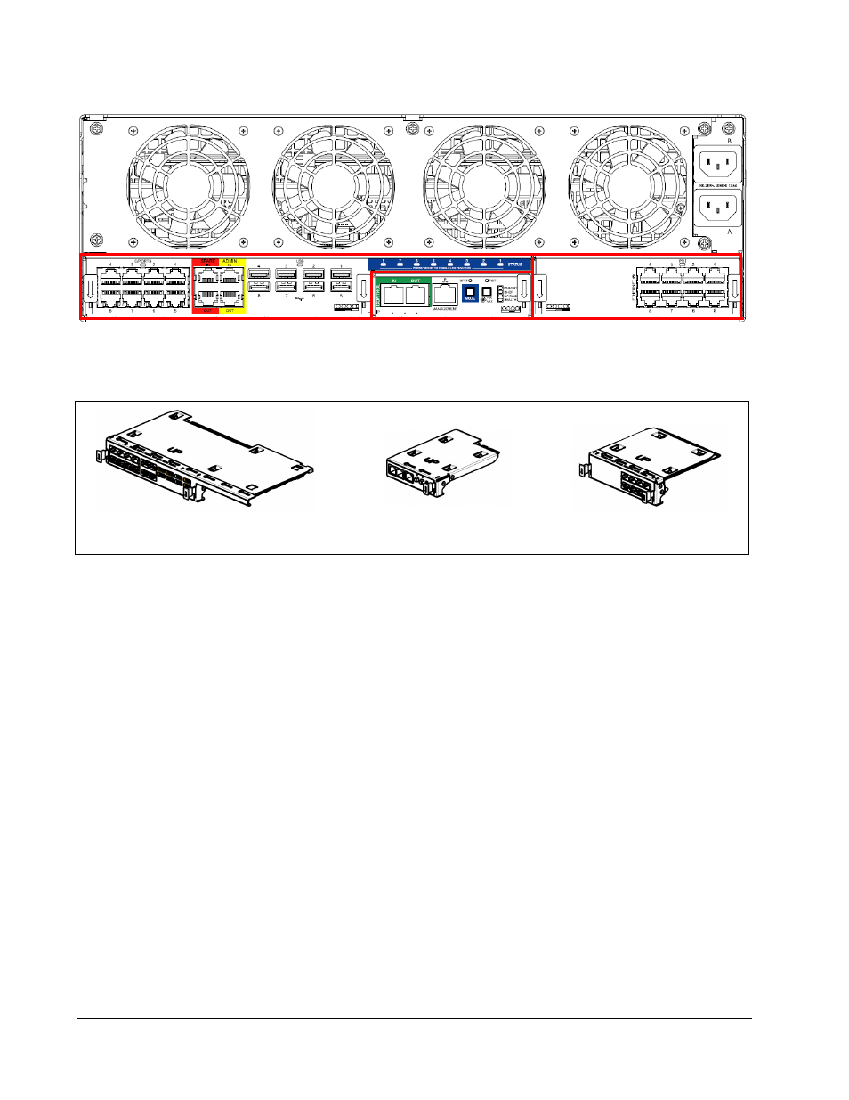
On the left in Figure 21, the Connect Module provides connectors for C/Ports, USB
ports, and sparing. On the right, the Network Module provides Ethernet connections.
In the center, the Remote Management Module provides network and daisy-chain
control connections, Chassis health indicators, and fan speed control. The Status
LEDs in the blue area above the Management Bay are shared between the sets of
connectors to provide information about each kind of connection to each Blade in a
manageable fashion.
Table 6 provides details of the features of the modules, and describes their
interactions. Note that some features are color-coded to show that their functions are
inter-related. For example, features coded blue are for monitoring the status of the
various connection ports on the R4300.
Figure 21 R4300 Module Bays
Figure 22 R4300 Modules
Connect Bay
Management Bay
Network Bay
Connect Module
Network Module
Management Module