Fiber optic extension system, Fiber transceiver, Fiber c/port – ClearCube R Series Pentium 4 User Manual
Page 38: Figure 9, Clearcube fiber transceiver, Figure 10, Clearcube fiber c/port
28 • ClearCube Architecture and Product Overview
ClearCube Product Manual and Installation Guide
Fiber Optic Extension System
The Fiber Optic Extension System adds fiber optic connectivity to the ClearCube
architecture via a pair of multi-mode fiber optic cables.
The system is compatible with ClearCube R Series Cages, BackPacks, and Blades. It
securely extends user desktops from centralized PC Blades to a distance as great as
500 meters over a pair of 62.5 micron multi-mode fibers. The system consists of two
components: the Fiber Transceiver and the Fiber C/Port.
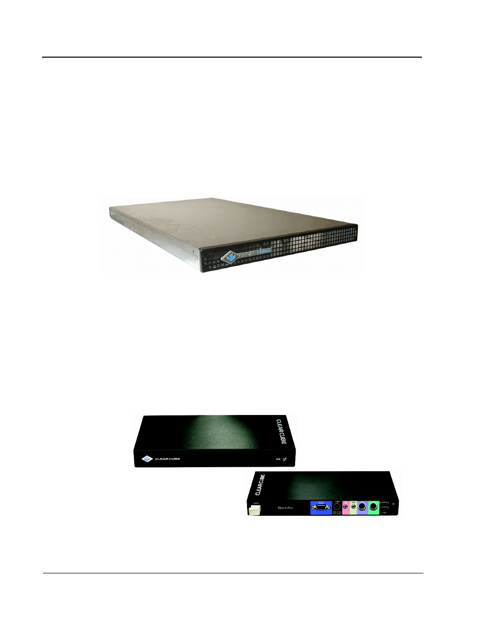
Fiber Transceiver
The Fiber Transceiver, shown in Figure 9, is a 1U high, rack-mounted device
designed to work specifically with the ClearCube architecture.
The Transceiver works by converting the copper-based C/Port signals leaving a
BackPack to fiber optic signals. A single 16-port Transceiver supports two standard
ClearCube Cages, or 16 PC Blades. The C/Port signals from the ClearCube Cage are
looped into the Transceiver over a short C/Port cable (
≤ 10 meters), one for each
Blade. The Transceiver then converts the signal from copper to fiber and sends it out
of the Transceiver through an industry standard MT-RJ connection.
Fiber C/Port
Figure 10 shows the Fiber C/Port. In the standard installation, the Fiber C/Port resides on
the user's desktop and has all the standard peripheral connections including USB, PS/2,
audio, and video. The Fiber C/Port is compatible with the Multi-Video Expander (MVX).
Figure 9 ClearCube Fiber Transceiver
Figure 10 ClearCube Fiber C/Port