Figure 24, Figure 25, Cage with blade switching backpack – ClearCube R Series Pentium 4 User Manual
Page 66: Table 10, Blade switching backpack connections, Table 10 blade switching backpack connections
56 • Cage and Blade Installation
ClearCube Product Manual and Installation Guide
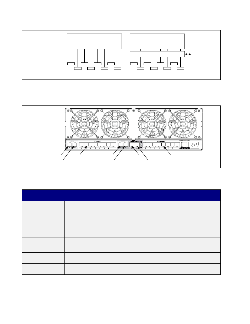
Refer to Figure 25 and Table 6 for specific descriptions of the connectors on the rear
of the BSBP.
Figure 24 Adding Remote Control Over PC Blade-to-C/Port Connections
Figure 25 Cage with Blade Switching BackPack
Table 10 Blade Switching BackPack Connections
Connector
Label
Cable
Color
Description
ADMIN IN
Yellow
The administrator’s C/Port connects here for access to the 1xN and Supervisor modes. The
BackPack routes this C/Port connection to various PC Blades as directed by the Switch
Manager. A single administrator can gain access to PC Blades in multiple Cages by
daisy-chaining this connection with the ADMIN OUT connector on the BackPacks of additional
Cages.
ADMIN OUT
Yellow
This connection links the Administrator’s C/Port to the ADMIN IN connection of the BackPack
on the next Cage when daisy-chaining multiple BackPacks. This allows a single administrator
control or supervise PC Blades in multiple Cages.
C/PORTS
Blue
These connections go out to each individual end user’s C/Port. Note that the numbers match
the Blade slot numbers on the front of the Cage.
SPARE OUT
Red
This connection links the Spare PC Blade connection to the SPARE IN connection of the
BackPack on the next Cage when daisy-chaining multiple BackPacks.
Cage with
8 PC Blades
C/Ports
Direct Connect Architecture
C/Ports
Cage with
8 PC Blades
Switch
Control
Blade Switching Matrix
Blade Switching Architecture
Admin In
Admin Out
Spare In
Spare Out
RS-485 Out
Control In
Ethernet
C/Ports