Connecting to a panelview operator terminal, What to do next, 9ć10 – Rockwell Automation 5000,D50006.2.10 PI INSTALLATION MANUAL User Manual
Page 123
Chapter 9
Connecting the I/O Link
9-10
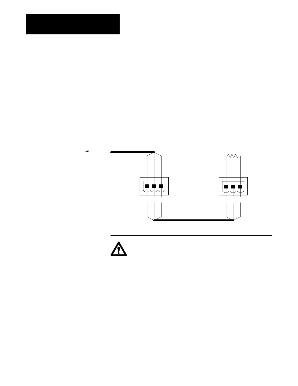
Figure 9.10 shows I/O link connections to PanelView Operator terminal
(2711 series) both as a middle device and as an end device on a link.
Terminal 1 connected internally for line 1 (blue-insulation conductor). The
middle terminal is connected internally for the shield. Terminal 3 is
connected internally for line 2 ( clear-insulated conductor). At each
PanelView Operator terminal, connect the shield drain wire of each cable
segment to give the shield continuity. However, never ground the shield at
a PanelView Operator terminal. At a PanelView Operator terminal
connected as an end device on a link, connect a 150-Ohm 1/4-Watt
termination resistor across the signal lines.
Figure 9.10
Connections to PanelView Operator Terminal
150
Ω
Blue
Shield
Clear
Blue
Shield
Clear
Blue
Shield
Clear
16614
PanelView
Operator
terminal
PanelView
Operator
terminal
To
Scanner
1
2 sh
1
2 sh
ATTENTION: Do not disconnect the connector on a middle
device when the system is operating because that would cause
discontinuity in the link and remove the termination. The
connection between terminals is inside the module.
After you have finished connecting the I/O link cabling, proceed to
chapter 10 to provide power to the I/O sub-system.
Connecting to a PanelView
Operator Terminal
What to do Next