Analog outputs (iod connector), Figure 38 - analog outputs circuit diagram – Rockwell Automation 2099-BMxx Kinetix 7000 High Power Servo Drive User Manual User Manual
Page 62
62
Rockwell Automation Publication 2099-UM001D-EN-P - December 2012
Chapter 3
Kinetix 7000 Connector Data
Analog Outputs (IOD Connector)
The two analog outputs (Analog_Out_1 and Analog_Out_2) are strictly for
troubleshooting and cannot be used to drive other loads.
The analog outputs provide 12-bit resolution (11 data bits, plus sign) of the gain
and filtering parameters within RSLogix software. In this way a data stream can
be displayed by a meter or scale as velocity, torque, or following error
information.
The ±10V outputs provide positive and negative direction range, with a null
setting of 0V. For example, ±10V range, with 0V = 0. The drive update rate for
these outputs is 125 μs, and is current limited to 25 mA.
Analog output functions are programmed in RSLogix software using a message
instruction. The default pin assignments and the default gain values for the
velocity, torque, and following error parameters are listed below.
A single pole low pass digital filter is provided for each analog output. The digital
filter frequency range is 1…4 kHz.
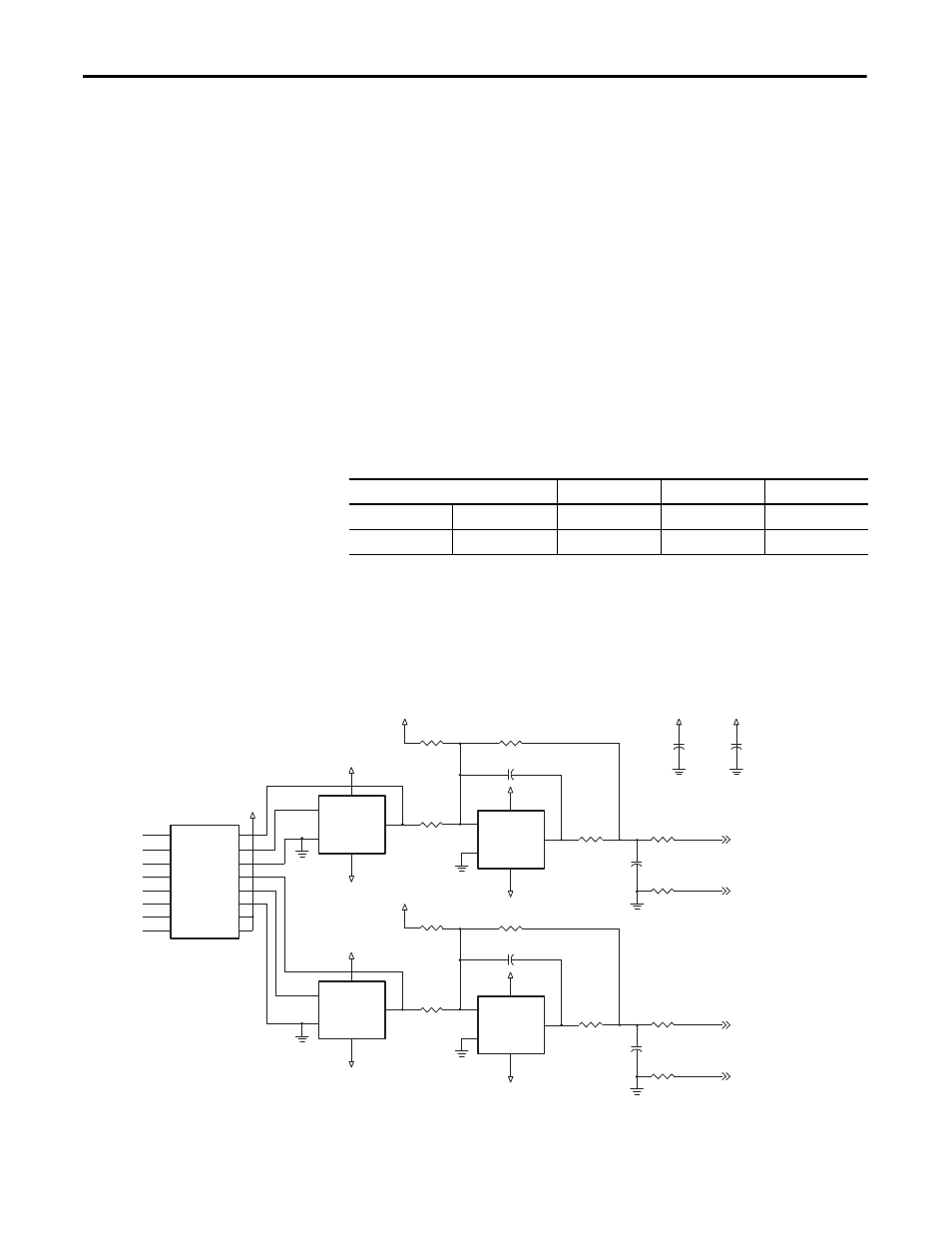
The schematic depicts the Analog Output circuits. It is provided as a reference
only.
Figure 38 - Analog Outputs Circuit Diagram
Signal
Default Pin
Parameter
Gain Value
Analog Output
Analog_Out_1
IOD-23
Velocity
0.0060
1V = 1000 rpm
Analog_Out_2
IOD-25
Torque
0.1
1V = 100% torque
IOD-26
IOD-25
–
+
V+
V–
–
+
V+
V–
3.9
μ
F
IOD-24
IOD-23
0.1
μ
F
0.1
μ
F
–
+
V+
V–
4.09
k
Ω
–
+
V+
V–
2.2
μ
F
3.9
μ
F
10
k
Ω
10
k
Ω
10
k
Ω
10
k
Ω
4.09
k
Ω
100
k
Ω
100
k
Ω
10
k
Ω
10
k
Ω
10
k
Ω
10
k
Ω
2.2
μ
F
Analog_Out_1
Analog_Out_1_Ret
Analog_Out_2
Analog_Out_2_Ret
VDD
SCLK
SDIN
SYNC
LDAC
SDO
CLR
GND
RFSA
IOUT1A
IOUT2A
RFSB
IOUT1B
IOUT2B
VRBFA
VRBFB