Power wiring examples – Rockwell Automation 2099-BMxx Kinetix 7000 High Power Servo Drive User Manual User Manual
Page 163
Rockwell Automation Publication 2099-UM001D-EN-P - December 2012
163
Interconnect Diagrams
Appendix B
Power Wiring Examples
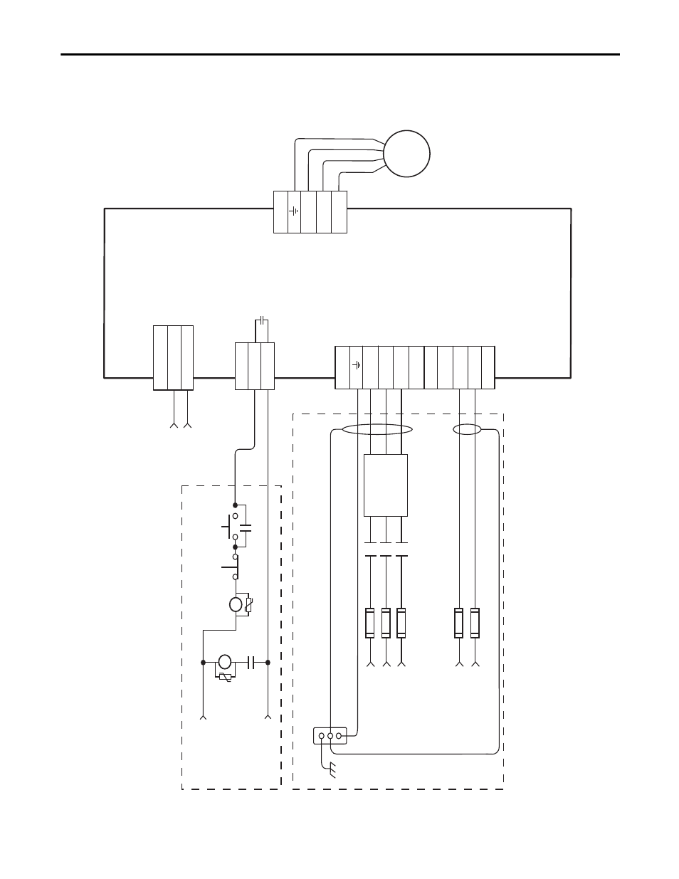
Figure 72 - Kinetix 7000 Drive AC Power Wiring
5
6
24V DC (Can also use 120/240V AC - see “General Purpose Relay (GPR Connector)” on page 61 for ratings. Connected components must match input power rating)*
M1*
CR1*
STOP*
STA
RT
(Drive Main Power On)*
GPR2+
GPR2-
GPR
CP_24VDC
CP_COM
CP
1
2
PE
U
V
W
T1
T2
T3
MP
R
S
T
DC+
DC-
0V
AC
120
V AC
240
V AC
TB
PE
L1
L2
L3
CR1*
CR1*
Input
Fusin
g *
See Note 2
Mot
or
Power Cables*
* Indicates
User Supp
lied
Compo
nent
360
° Shieldin
g of
Power
Wirin
g
Required to Comply with EMC Requirements
Bonded
Cabinet
Ground Bus *
Three Phase Motor Power Connections
* Indicates
User Supp
lied
Compo
nent
Thre
e-phase
AC Input and DC Bus Output Connections
Sing
le-p
hase
Fan Power Connections See Note 9
Add
itional con
nectio
ns requ
ired
,
but
not
shown
in this diagram:
1. Motor Brake (if used) and Feedback 2. Machine Feedback and Drive I/O 3. Drive Communications
Contro
l
Stop String See Note 8
Control P
ower
DC Input Connections
+24V DC
Control Power *
See Note 7
Th
ree-pha
se
Input
(+10/-15%) 460VAC RMS,
50/60 Hz See Note 1
Single-pha
se
Input
(+10/-15%)
120V or 240 VAC RMS,
50/60 Hz
(120V AC wiring shown)
Thre
e-Phase Contactor *
(M1 in Control String)
Th
ree-phase
AC Line Filter * See Note 3
Kinetix 7000 Drive
2099-BM
xx-S
Motor*
Note 4