Rockwell Automation 2099-BMxx Kinetix 7000 High Power Servo Drive User Manual User Manual
Page 38
38
Rockwell Automation Publication 2099-UM001D-EN-P - December 2012
Chapter 2
Install the Kinetix 7000 Drive System
When mounting your shunt module inside the enclosure, follow these additional
guidelines.
• Metal-clad modules can be mounted anywhere in the dirty zone, but as
close to the Kinetix 7000 system as possible.
• Shunt power wires can be run with motor power cables.
• Keep unshielded wiring as short as possible. Keep shunt wiring as flat to
the cabinet as possible.
• Separate shunt power cables from other sensitive, low voltage signal cables.
• The shunt module watts dissipation must be included in the Kinetix 7000
system heat dissipation calculation for selecting an enclosure.
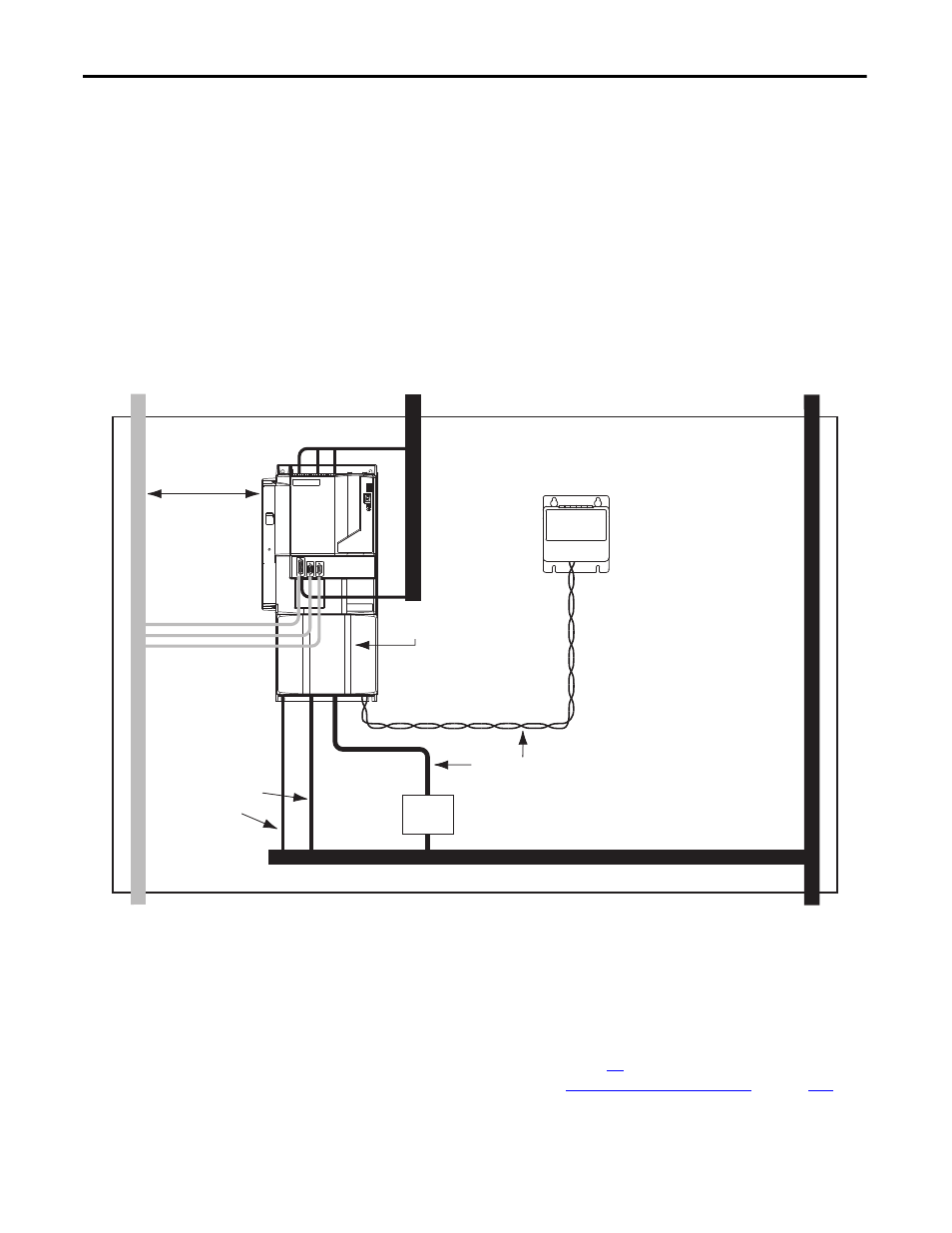
Figure 15 - External Shunt Resistor Inside the Enclosure
Motor Brake and Thermal Switch
The thermal switch and brake are mounted inside the motor, but how you
connect to the axis module depends on the motor series.
See Wire Motor Output Power on page
for wiring guidelines specific to your
drive/motor combination, and to
for
the interconnect diagram of your drive/motor combination.
C1
C1
VD
D3
D2
D1
VD
VD
D1
D2
Kinetix 7000
Dirty Wireway
Clean Wireway
No sensitive
equipment within
150 mm (6.0 in.)
Motor Power Cables
Very dirty connections segregated (not
in wireway)
Route 24V DC I/O
Shielded Cable
Route Encoder/Analog/Registration
Shielded Cables
Observe minimum clearance
requirements for shunt
module spacing.
Enclosure
Shunt Module
Shunt Wiring Methods:
Twisted pair in conduit (1st choice).
Shielded twisted pair (2nd choice).
Twisted pair, 2 twists per foot min.
(3rd choice).
I/O and Feedback
Cables
AC Line
Filter