Apply power to the drive – Rockwell Automation 2099-BMxx Kinetix 7000 High Power Servo Drive User Manual User Manual
Page 126
126
Rockwell Automation Publication 2099-UM001D-EN-P - December 2012
Chapter 5
Configure and Startup the Kinetix 7000 Drive System
Apply Power to the Drive
This procedure assumes that you have completed the following tasks:
• Wired your Kinetix 7000 drive.
• Connected your Logix controller, SERCOS interface module fiber-optic
connections to your Kinetix 7000 drive.
• Configured and verified a RSLogix 5000 program.
• Connected the motor power and motor feedback cables to your Kinetix
7000 drive.
Refer to the Line Interface Module Installation Instructions, publication
when troubleshooting the LIM status indicators, and for the
location of LIM circuit breakers, connectors, and status indicators.
Follow these steps to apply power to the Kinetix 7000 system.
1. Determine your source of control power.
2. Verify the status of the drive logic power status indicator.
SHOCK HAZARD: To avoid hazard of electrical shock, complete all mounting
and wiring prior to applying power. Once power is applied, connector terminals
may have voltage present even when not in use.
ATTENTION: To avoid personal injury or damage to equipment, disconnect the
load to the motor. Make sure each motor is free of all linkages when initially
applying power to the system.
If Your Control Power
Then
Is sourced from a LIM
module
1. Verify that the LIM CB1, CB2, and CB3 are in the OFF position.
2. Apply three-phase input power to the LIM VAC Line connector.
3. Set CB3 to the ON position.
4. Set CB2 to the ON position.
5. Go to main
step 2
.
Is not sourced from a LIM
module
1. Apply 24V DC control power to the drive (CP connector).
2. Go to main
step 2
.
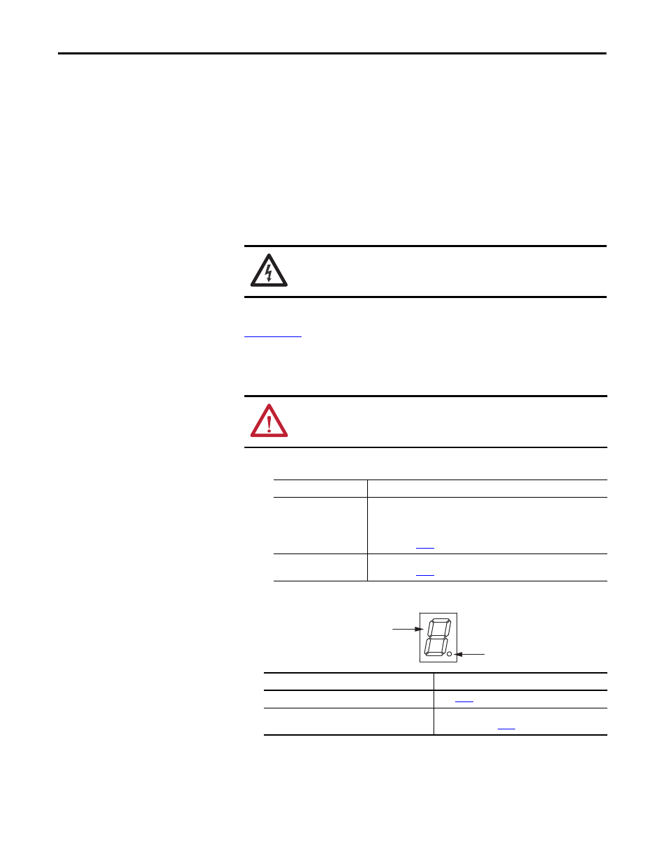
If the Logic Power Status Indicator is
Then
ON Go
to
step 3
.
Not ON
1. Check your control power connections.
2. Go back to main
.
Logic Power Status Indicator
Seven-segment Fault Status Indicator