Rockwell Automation 2099-BMxx Kinetix 7000 High Power Servo Drive User Manual User Manual
Page 127
Rockwell Automation Publication 2099-UM001D-EN-P - December 2012
127
Configure and Startup the Kinetix 7000 Drive System
Chapter 5
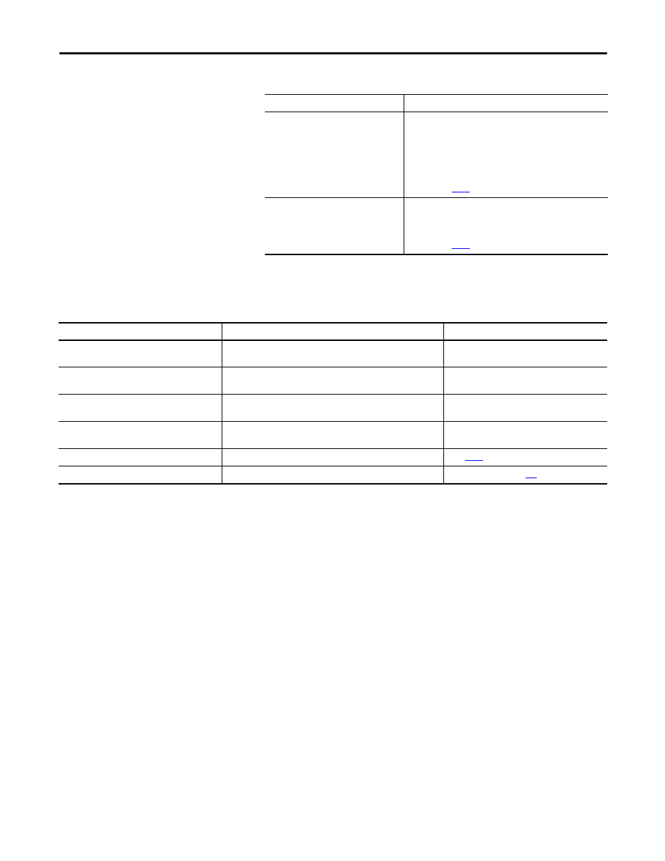
3. Define the three-phase input power as described below.
4. Observe the seven-segment fault status indicator display on the drive.
The status indicator will first flash the SERCOS node address, then cycle
through phases until final configuration (phase 4) is reached.
If Your Three-phase Power
Then
Is sourced from a LIM module
1. Set the LIM CB1 to the ON position.
2. Verify that the LIM, IPL, and OPL connections for phase-to-
phase voltage is 324…528V AC (460V).
3. Verify that the input voltage at terminals R (L1), S (L2), and T
(L3) on the Kinetix 7000 drive is 324…528V AC (460V).
4. If used, verify that the Kinetix 7000 drive Hardware Enable
Input signal (IOD pin 2) for each axis is off.
5. Go to main
step 4
.
Is not sourced from a LIM module
1. Apply 324...528V AC (460V) input power to the Kinetix 7000
drive R (L1), S (L2), and T (L3) input terminals.
2. If used, verify that the Kinetix 7000 drive Hardware Enable
Input signal (IOD pin 2) is off.
3. Go to main
step 4
.
Kinetix 7000 Drive Status Indicator
Status
Do This
Actively cycling (phase 0)
The drive is looking for a closed SERCOS ring. Wait for phase 1 or take
corrective action until you reach phase 1.
Check fiber-optic connections.
Displaying a fixed 1 (phase 1
The drive is looking for active nodes. Wait for phase 2 or take corrective
action until you reach phase 2.
Check node addressing.
Displaying a fixed 2 (phase 2)
The drive is configuring nodes for communication. Wait for phase 3 or
take corrective action until you reach phase 3.
Check program motor and drive configuration
against installed hardware.
Displaying a fixed 3 (phase 3)
The drive is configuring device specific parameters. Wait for phase 4 or
take corrective action until you reach phase 4.
Check motor catalog number against selection.
(1)
Displaying a fixed 4 (phase 4)
The drive is configured and active.
Go to
step 5
.
Flashing an E followed by two numbers
Drive is faulted.
Go to Error Codes on page
.
(1) To get diagnostic information from the module, highlight the module name in RSLogix 5000 software. A Pseudo Key Failure often indicates that the motor selection does not match the motor installed.