Configuration flags, Operational mode (ctr, Config.operationalmode_0 through ctr – Rockwell Automation 1769-HSC Compact High Speed Counter Module User Manual
Page 82: Config.operationalmode_2)
82
Rockwell Automation Publication 1769-UM006E-EN-P - July 2013
Chapter 4
Module Configuration, Output, and Input Data
Configuration Flags
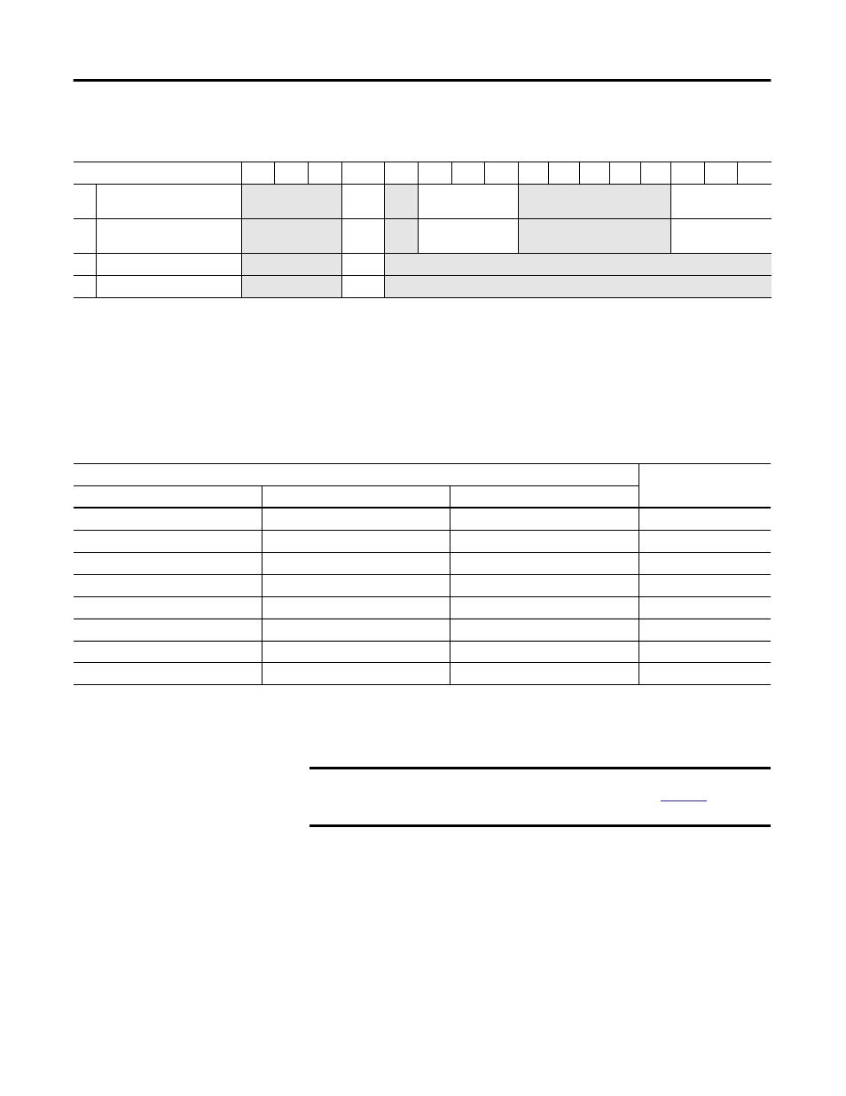
Operational Mode (Ctr
n
Config.OperationalMode_0 through
Ctr
n
Config.OperationalMode_2)
These bits apply to Counters 0 and 1 only.
This value determines how the A
0 or A1 and B0 or B1 inputs are decoded when
assigned to counter 0 or counter 1.
Configuration Array Words
15
14
13
12
11
10
09
08
07
06
05
04
03
02
01
00
15 Counter 0 Configuration Flags
Not used
Linear
Not
used
Storage mode
Not used
Operational mode
25 Counter 1 Configuration Flags
Not used
Linear
Not
used
Storage mode
Not used
Operational mode
35 Counter 2 Configuration Flags
Not used
Linear
Not used
45 Counter 3 Configuration Flags
Not used
Linear
Not used
Set bit
For function
CtrnConfig.OperationalMode_2
CtrnConfig.OperationalMode_1
CtrnConfig.OperationalMode_0
0
0
0
Pulse internal direction
0
0
1
Pulse external direction
1
0
0
Quadrature encoder X1
1
0
1
Quadrature encoder X2
1
1
0
Quadrature encoder X4
0
1
0
Up/Down Pulses
0
1
1
reserved
1
1
1
reserved
TIP
The Ctr1Config.OperationalMode bits are reserved if the Number of
Counters equals 1. Attempting to set reserved bits will result in a
configuration error.
IMPORTANT
Do not change this value while the counter is enabled. Attempting to do
so will result in a BadModConfigUpdate error. See
for a list of
prohibited settings.