Input filtering – Rockwell Automation 1769-HSC Compact High Speed Counter Module User Manual
Page 20
20
Rockwell Automation Publication 1769-UM006E-EN-P - July 2013
Chapter 2
Module Operation
Input Filtering
In many industrial environments, high frequency noise can be inadvertently
coupled to the sensor wires. The module can help reject some noise by means of
built-in filters. Inputs are filtered by means of user-selectable, low-pass filters
(1)
set up during module configuration.
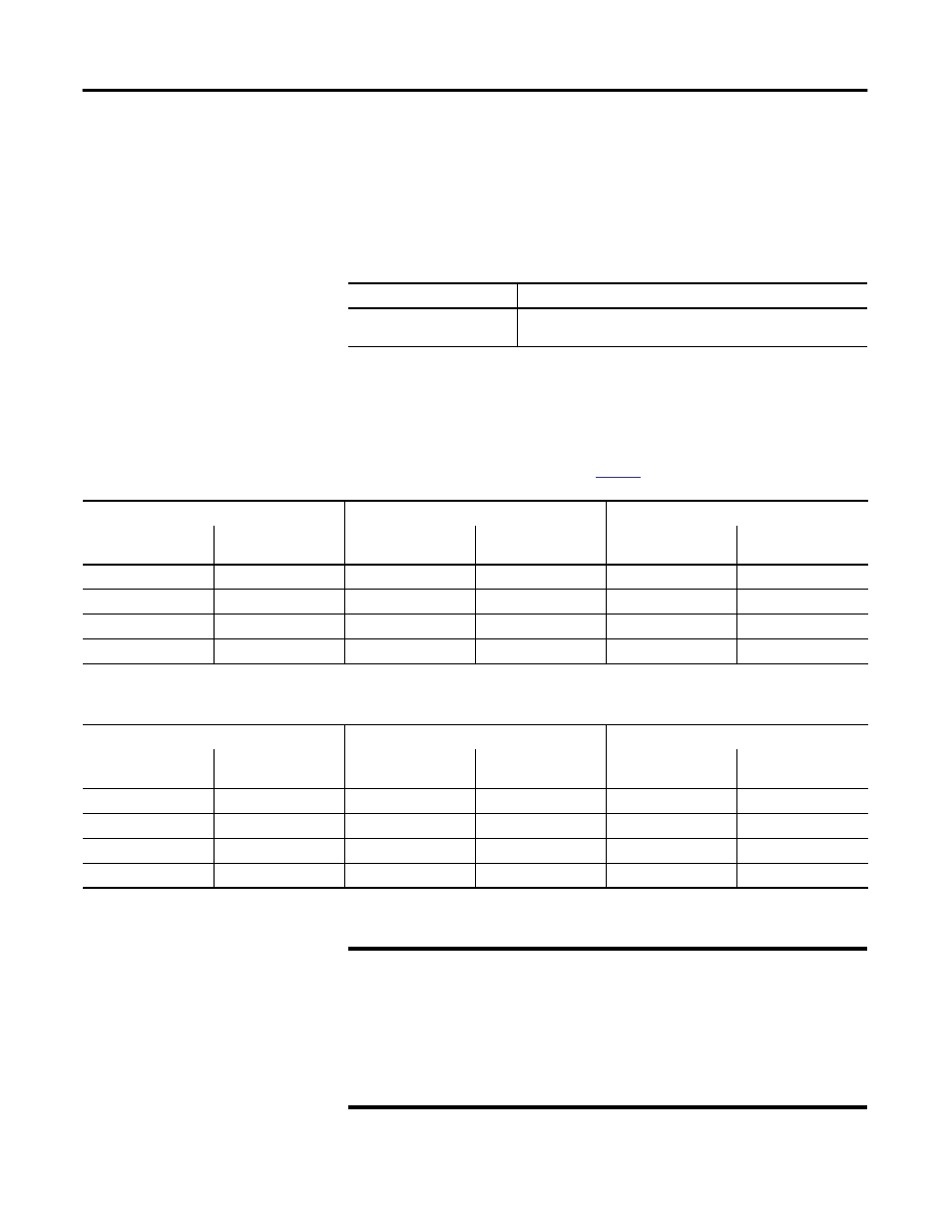
The available nominal pulse width filters are shown in the table.
The filters are selected for each input in the Filter Selection word of the
module’s configuration array.
(1) Low-pass filters block frequencies above the threshold frequency.
Input
Filter
A0, A1, B0, B1, Z0, Z1
5 ms, 500
s, 10 s, no filter
(7.1 ms, 715
s, 18.5 s, no filter for the packaged controller)
TIP
The input state bits (InputStateA0 through InputStateZ1) reflect the
filter’s inputs, but are NOT affected by the signal inhibit or invert
operations described on
.
Nom Filter Settings
Max Guaranteed Blocked Pulse Width
Min Guaranteed Pass Pulse Width
Pulse Width
Equivalent
Frequency
(1)
Pulse Width
Equivalent
Frequency
(1)
Pulse Width
Equivalent
Frequency
(1)
No filter
1 MHz
N/A
N/A
250 ns
2 MHz
10 µs
50 kHz
7.4 µs
67.5 kHz
25 µs
20 kHz
500 µs
1 kHz
370 µs
1.35 kHz
1.25 ms
400 Hz
5 ms
100 Hz
3.7 ms
135 Hz
12.5 ms
40 Hz
(1) Equivalent frequency assumes a perfect 50% duty cycle and are for reference purposes only. Hence, the no-filter setting is guaranteed to pass 4 MHz even though the
module’s maximum is 1 MHz. This lets the sensor and wiring to attenuate the pulse to 25% duty cycle while the module maintains pulse recognition.
Nom Filter Settings
Max Guaranteed Blocked Pulse Width
Min Guaranteed Pass Pulse Width
Pulse Width
Equivalent
Frequency
(1)
Pulse Width
Equivalent
Frequency
(1)
Pulse Width
Equivalent
Frequency
(1)
No filter
250 kHz
0.83 µs
600 kHz
2.5 µs
200 kHz
18.5 µs
27 kHz
12.3 µs
40.5 kHz
28.6 µs
17.5 kHz
715 µs
700 Hz
495 µs
1.01 kHz
1.25 ms
400 Hz
7.1 ms
70 Hz
4.95 ms
101 Hz
12.5 ms
40 Hz
(1) Equivalent frequency assumes a perfect 50% duty cycle and are for reference purposes only. Hence, the no-filter setting is guaranteed to pass 4 MHz even though the
module’s maximum is 1 MHz. This lets the sensor and wiring to attenuate the pulse to 25% duty cycle while the module maintains pulse recognition.
IMPORTANT
The built-in filters are simple, averaging, low-pass filters. They are
designed to block noise pulses of width equal to the values presented in
Table Filter Pulse Width and Frequency. Applying full amplitude, 50%
duty cycle signals that are of frequency above the selected filter’s
threshold frequency can result in an average value signal of sufficient
amplitude to turn the input on. A transition from no input to the full
amplitude, 50% duty cycle signal (or back to no signal) can result in
inadvertent input transitions.