Input state (inputstatea0 through inputstatez1), Readback (readback.0 through readback.15), Status flags – Rockwell Automation 1769-HSC Compact High Speed Counter Module User Manual
Page 101
Rockwell Automation Publication 1769-UM006E-EN-P - July 2013
101
Module Configuration, Output, and Input Data
Chapter 4
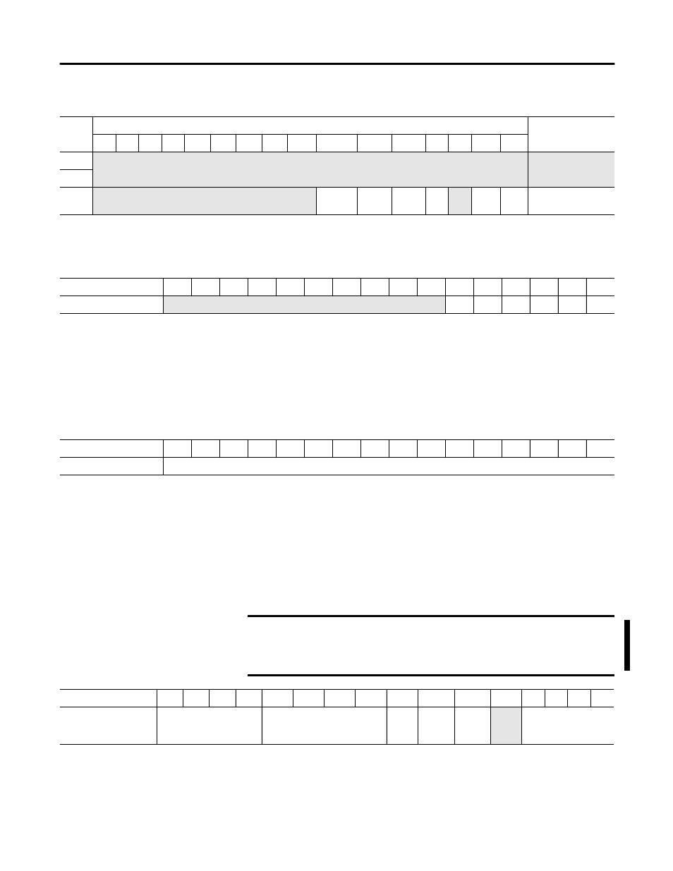
Input State (InputStateA0 through InputStateZ1)
This word indicates the state of the real (physical) inputs after filtering.
• 1 = On
• 0 = Off
Readback (Readback.0 through Readback.15)
This input word reflects the counter’s module-directed status of all 16 outputs,
real and virtual.
• 1 = On
• 0 = Off
Status Flags
32
Not used
Not used
33
34
Not used
C3PW
RV
IC
ID
W
CUdf
COvf
Counter 3 Status
Flags
Table 17 - Input Array - L23E Packaged Controller Enbedded HSC (Continued)
Word
Bit
Function
15
14
13
12
11
10
09
08
07
06
05
04
03
02
01
00
Input Array Word 0
15
14
13
12
11
10
09
08
07
06
05
04
03
02
01
00
Input State
Not used
Z1
B1
A1
Z0
B0
A0
Input Array Word 1
15
14
13
12
11
10
09
08
07
06
05
04
03
02
01
00
Readback
Readback.0 through Readback.15
IMPORTANT
For the L23E packaged controllers embedded HSC, the ranges referred to
in this section are numbered 0…3 instead of 12…15. The ranges in this
section apply to only the 1769-HSC module and the CMX 5370 L2
packaged controllers embedded HSC.
Input Array Word 2
15
14
13
12
11
10
09
08
07
06
05
04
03
02
01
00
Status Flags
InvalidRangeLimit12
through
InvalidRangeLimit15
InvalidCtrAssignToRange12
through
InvalidCtrAssignToRange15
Gen
Error
Invalid
Output
Mod
Config
Not
used
Out0Overcurrent
through
Out3Overcurrent