Hardware features, Figure 1 - hardware features – Rockwell Automation 1769-HSC Compact High Speed Counter Module User Manual
Page 13
Rockwell Automation Publication 1769-UM006E-EN-P - July 2013
13
Module Overview
Chapter 1
Hardware Features
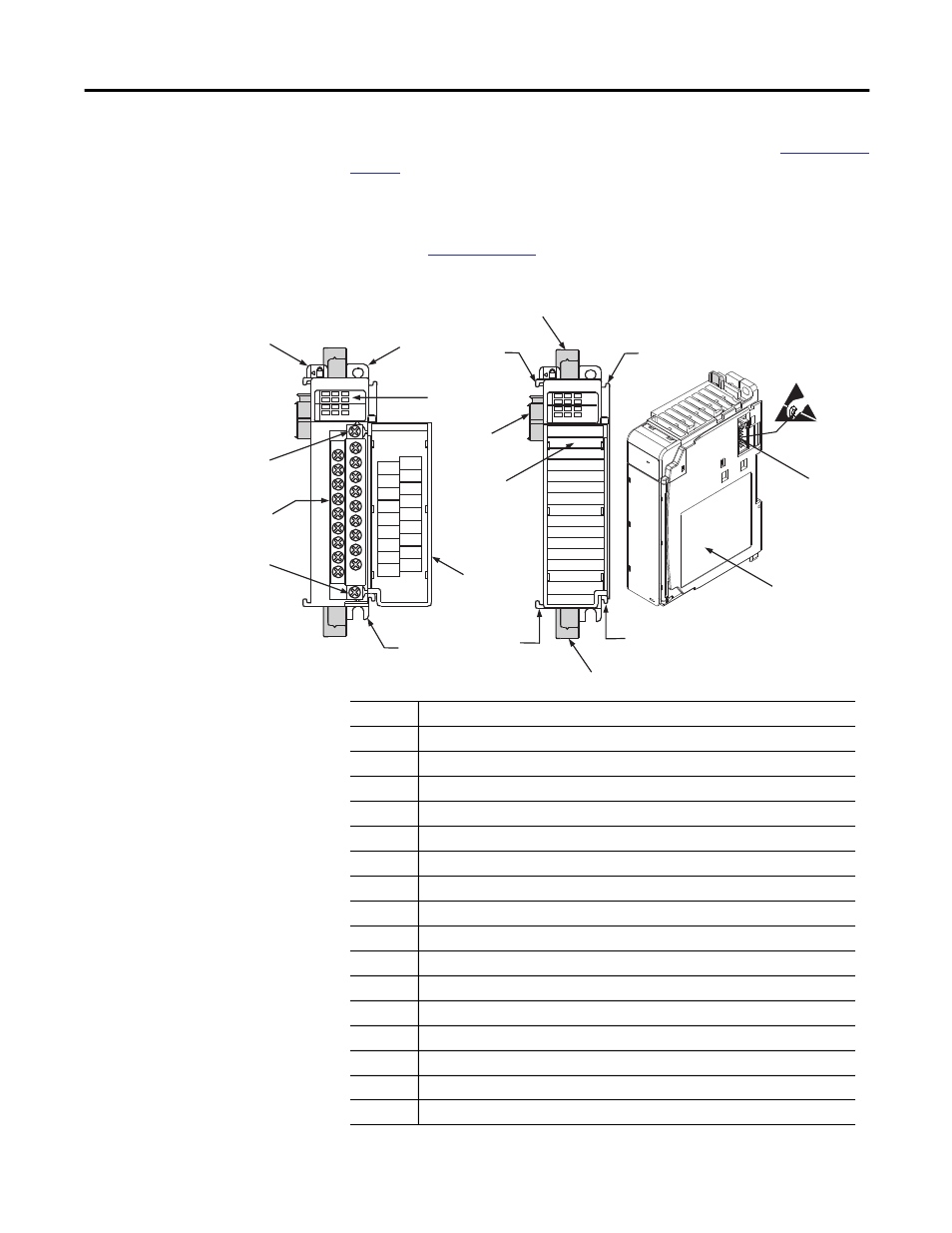
The module’s hardware features are illustrated in Figure 1. Refer to
for detailed information on installation and wiring.
For information about the packaged controllers’ hardware features, see the
CompactLogix Packaged Controllers Quick Start and User Manual,
publication
Figure 1 - Hardware Features
1769-HSC
DANGER
Do Not Remove RTB Under Power
Unless Area is Non-Hazardous
Ensure Adjacent
Bus Lever is Unlatched/Latched
Before/After
Removing/Inserting Module
OUT 2
A1-
Z1-
OUT DC
COM
B0-
Z0-
B1-
OUT 0
OUT DC
+5V/24V
A0+
Z0+
B1+
OUT 3
OUT 1
B0+
A1+
Z1+
A0-
High Speed Counter
0
2
1
3
A0
B0
A1
B1
Z0
Z1
IN
OUT
High Speed Counter
0
2
1
3
A0
B0
A1
B1
Z0
Z1
IN
OUT
1
2a
3
4
2b
5b
5
5a
9a
8a
6b
7
8b
9b
8b
10
6a
8a
45271
Item
Description
1
Bus lever
2a
Upper panel mounting tab
2b
Lower panel mounting tab
3
Module status indicators (6 Input, 4 Output, 1 Fuse, 1 OK)
4
Module door with terminal identification label
5
Removable terminal block (RTB) with finger-safe cover
5a
RTB upper-retaining screw
5b
RTB lower-retaining screw
6a
Movable bus connector (bus interface) with female pins
6b
Stationary bus connector (bus interface) with male pins
7
Nameplate label
8a
Upper tongue-and-groove slots
8b
Lower tongue-and-groove slots
9a
Upper DIN-rail latch
9b
Lower DIN-rail latch
10
Write-on label for user identification tags