Module diagnostics, Power-up diagnostics – Rockwell Automation 1769-HSC Compact High Speed Counter Module User Manual
Page 112
112
Rockwell Automation Publication 1769-UM006E-EN-P - July 2013
Chapter 5 Diagnostics and Troubleshooting
Module Diagnostics
The 176-HSC module offers power-up, configuration, and post configuration
diagnostics.
Power-up Diagnostics
At module powerup, a series of internal diagnostic tests are performed. These
diagnostic tests must be successfully completed or the OK status indicator
remains off and a module error results and is reported to the controller.
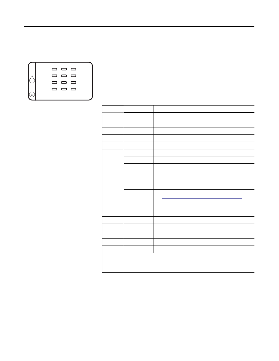
45272
IN
OUT
0
2
FUSE
1
3
OK
A0
B0
Z0
A1
B1
Z1
High Speed Counter
Table 18 - Diagnostic Indicators
Indicator
Color
Indicates
0 OUT
Amber
ON/OFF logic status of output 0
1 OUT
Amber
ON/OFF logic status of output 1
2 OUT
Amber
ON/OFF logic status of output 2
3 OUT
Amber
ON/OFF logic status of output 3
FUSE
Red
Overcurrent
OK
Off
No power is applied.
Red (briefly)
Performing self-test.
Solid Green
OK, normal operating condition.
Flashing Green
OK, module in Program or Fault mode.
Solid Red or
Amber
Hardware error. Cycle power to the module. If problem persists,
replace the module.
Flashing Red
Recoverable fault. Reconfigure, reset, or perform error recovery.
See
Non-critical versus Critical Module Errors on page 113
. The
OK status indicator flashes red for all of the error codes in the
Configuration Error Codes table on page 117
A0
Amber
ON/OFF status of input A0
A1
Amber
ON/OFF status of input A1
B0
Amber
ON/OFF status of input B0
B1
Amber
ON/OFF status of input B1
Z0
Amber
ON/OFF status of input Z0
Z1
Amber
ON/OFF status of input Z1
ALL ON
Possible causes for all status indicators to be on include the following:
• Bus Error has occurred: Controller hard fault. Cycle power.
• During upgrade of controller: Normal. Do not cycle power during the upgrade.
• All status indicators will flash on briefly during power-up. This is normal.