Connect the module to the mounting base – Rockwell Automation 1734-IE4S POINT Guard I/O Safety Modules User Manual User Manual
Page 55
Rockwell Automation Publication 1734-UM013J-EN-P - July 2014
55
Install the Module
Chapter 4
Follow these steps to install the mounting base.
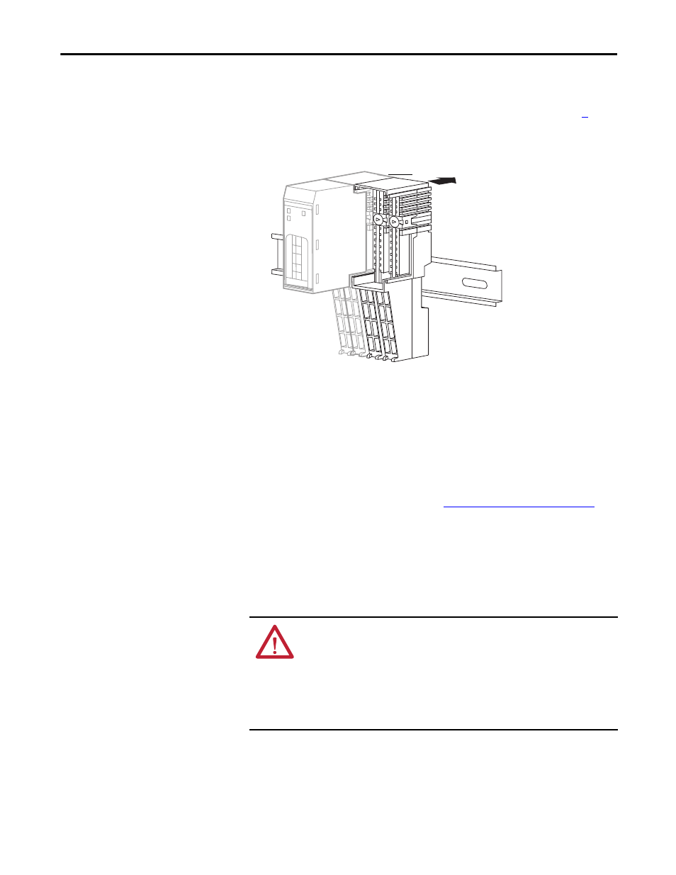
1. Position the mounting base as shown in the illustration below step
2. Slide the mounting base down, allowing the interlocking side pieces to
engage the adjacent module, power supply, or adapter.
3. Press firmly to seat the mounting base on the DIN rail until the mounting
base snaps into place.
Refer to the terminal base installation instructions for detailed information on
installation and removal. Always follow instructions and torque specifications in
terminal base installation instructions. See
Additional Resources on page 13
terminal base installation publications.
Connect the Module to the Mounting Base
Install the module before or after installing the mounting base.
TIP
In high vibration environments, install slide locks to prevent movement of the
mounting base along the DIN rail.
WARNING: When you insert or remove the module while backplane power is
on, an electrical arc can occur. This could cause an explosion in hazardous
location installations. Be sure that power is removed or the area is
nonhazardous before proceeding.
Repeated electrical arcing causes excessive wear to contacts on both the module
and its mating connector. Worn contacts may create electrical resistance that can
affect module operation.
Slide the mounting base to let the
interlocking side pieces engage
the adjacent module or adapter.
31868-M