Rockwell Automation 1734-IE4S POINT Guard I/O Safety Modules User Manual User Manual
Page 128
128
Rockwell Automation Publication 1734-UM013J-EN-P - July 2014
Chapter 7
Configuring Safety Connections between a GuardLogix Controller and POINT Guard I/O Modules on a DeviceNet Network
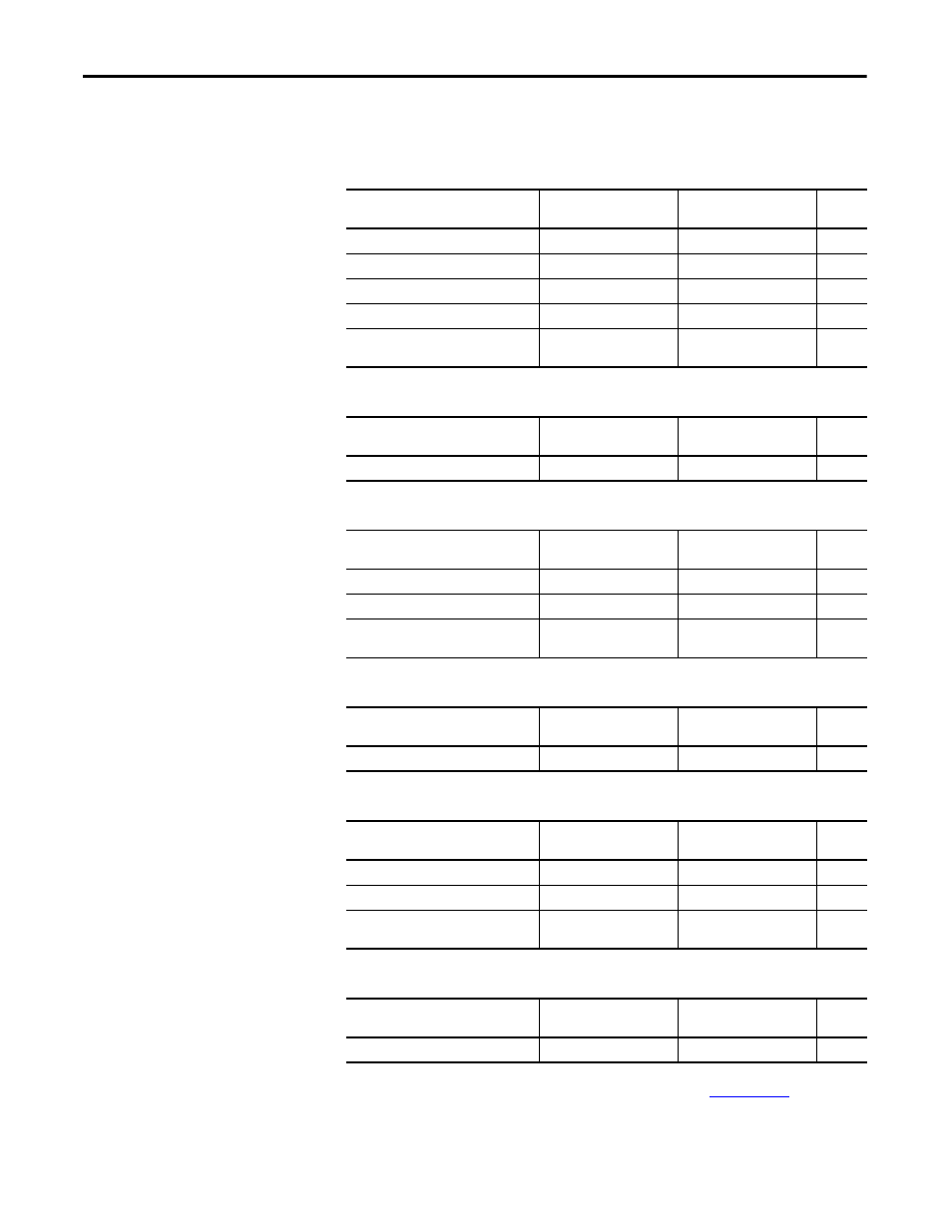
8. Determine which assemblies you want to connect to and set the safety
input and output assemblies by using the following tables.
Individual members of each assembly are listed in
Table 5 - 1734-IB8S Input Assemblies
Safety Input Connection
Input Assembly Safety
Input Number
Input Assembly Safety
Output Number
Size
Safety
516 (204h)
199 (C7h)
1
Safety + Combined Status – Muting
788 (314h)
199 (C7h)
2
Safety + Pt. Status
548 (224h)
199 (C7h)
2
Safety + Pt. Status – Muting
820 (334h)
199 (C7h)
3
Safety + Pt. Status – Muting – Test
Output
868 (364h)
199 (C7h)
4
Table 6 - 1734-IB8S Output Assemblies
Safety Output Connection
Output Assembly Safety
Input Number
Output Assembly Safety
Output Number
Size
Test
199 (C7h)
33 (21h)
1
Table 7 - 1734-OB8S Input Assemblies
Safety Input Connection
Input Assembly Safety
Input Number
Input Assembly Safety
Output Number
Size
Safety Output Status
580 (244h)
199 (C7h)
1
Output Status + Monitor
1028 (404h)
199 (C7h)
2
Safety Monitor + Combined Status +
Power
1044 (414h)
199 (C7h)
2
Table 8 - 1734-OB8S Output Assemblies
Safety Output Connection
Output Assembly Safety
Input Number
Output Assembly Safety
Output Number
Size
Test
199 (C7h)
564 (234h)
1
Table 9 - 1734-IE4S Input Assemblies
Safety Input Connection
Input Assembly Safety
Input Number
Input Assembly Safety
Output Number
Size
Safety + Status
402 (192h)
199 (C7h)
9
Safety + Status + Alarms
786 (312h)
199 (C7h)
13
Safety + Status + Process Status + Fault
Reason + Alarms
802 (322h)
199 (C7h)
18
Table 10 - 1734-IE4S Output Assemblies
Safety Output Connection
Output Assembly Safety
Input Number
Output Assembly Safety
Output Number
Size
Safety Tachometer
199 (C7h)
770 (302h)
1