Example fault queue read emulated block transfer – Rockwell Automation 1203-CN1 ControlNet Communications Module 1203-CN1 User Manual
Page 72
Publication 1203-5.13 – February, 2002
6-6
Using Messages
Example Fault Queue Read Emulated Block Transfer
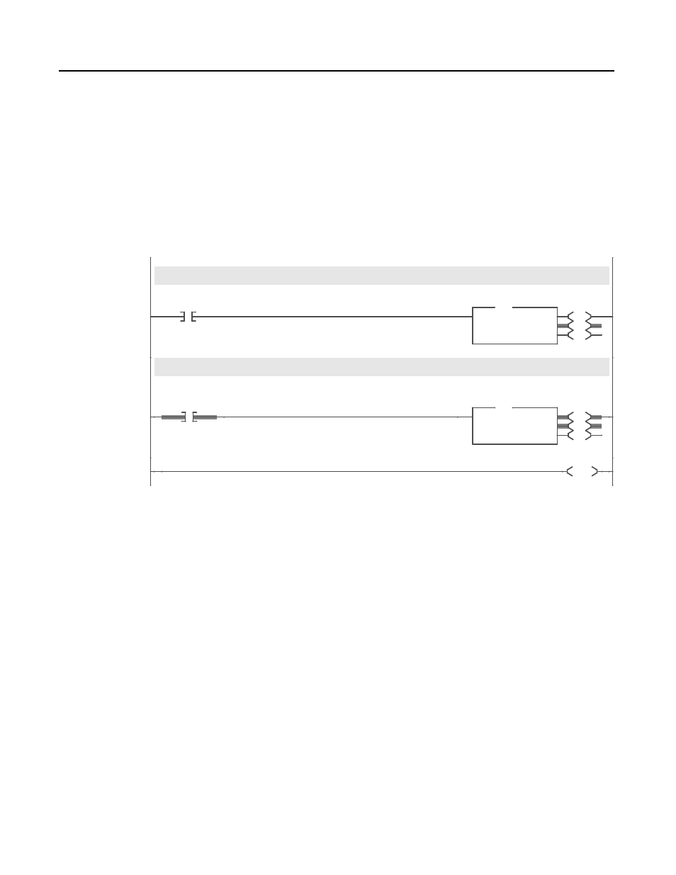
Figure 6.8 contains an example of an emulated block transfer. In
emulated block transfers, the first rung always writes the data from
the drive to the N:40 file in the module; the second rung then reads
the data from this file.
Important: You can activate only one emulated block transfer
message at a time. If more than one message is active, data may be
processed out of order and inaccurate results may be supplied.
Figure 6.8
Read Fault Queue Entry #1 Logic
The MSG dialog box in Figure 6.9 specifies the configuration for the
Write Probe message. Note the following:
•
In the Data Table Address field in the This PLC-5 section,
N22:0 is specified. This is where the results will be reported.
•
In the Size in Elements field in the This PLC-5 section, 10 is
specified. The response will be 10 elements.
•
In the Data Table Address field in the Target Device section,
N40:0 is specified. This is the location where the fault queue data
will be stored.
Important: If you refer to Appendix C, N-File Structure, you will
find that block transfer emulation data is contained in N40:0 –
N40:63.
Block Transfer Emulation
This rung sends a message that instructs the 1203-CN1 what information to gather from the 1305 AC Drive. The message can be 3 to
64 words long.
0002
I:000
17
User
Input
EN
DN
ER
MSG
Read/Write Message
Control
MG15:2
Setup Screen
MSG
When the previous MSG instruction completes, this rung reads the information requested from the 1203-CN1. The response message
can be 3 to 64 words long.
0003
MG15:2
DN
Write Probe
Message
Completed
EN
DN
ER
MSG
Read/Write Message
Control
MG15:3
Setup Screen
MSG
0004
END